For peripherals, the RP2040 provides two I2C controllers, two SPI controllers, and two UARTs that are multiplexed across the GPIO (check the pinout for compatibility). There are 16 PWM channels, and each pin has a channel it can be assigned to.
Specifications
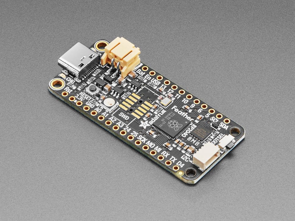
- Board dimensions: 2.0" x 0.9" x 0.28" (50.8mm x 22.8mm x 7mm) without headers
- Weight: 5 grams
- RP2040 32-bit Cortex M0+ dual-core running at ~125 MHz @ 3.3V logic and power
- 264 KB RAM
- 8 MB SPI Flash chip for file storage and CircuitPython/MicroPython code (no EEPROM)
- 21 GPIO pins with the following capabilities:
- Four 12-bit ADCs (one more than Pico)
- Two I2C, two SPI, and two UART peripherals (standard Feather layout for main interface)
- 16 PWM outputs for servos, LEDs, etc.
- 8 digital GPIO pins consecutive for maximum PIO compatibility
- Built-in 200mA+ LiPoly charger with status LED
- Pin #13 red LED for general-purpose use
- RGB NeoPixel for full-color indication
- STEMMA QT connector for plug-and-play I2C devices
- Reset button and Bootloader select button for easy restarts
- 3.3V Power/enable pin
- Four mounting holes
- 24 MHz crystal for accurate timing
- 3.3V regulator with 500mA peak current output
- USB Type-C connector for ROM USB bootloader and serial debugging
Bootloader
The RP2040 includes a permanent ROM USB UF2 bootloader. To program new firmware, hold down the BOOTSEL button while plugging in USB (or pull the RUN/Reset pin low) and it will appear as a USB disk drive. Simply drag-and-drop the firmware file. Unlike some other boards, you don’t double-click reset — instead, hold BOOTSEL during boot to enter the bootloader mode.
For peripherals, the RP2040 provides two I2C controllers, two SPI controllers, and two UARTs that are multiplexed across the GPIO (check the pinout for compatibility). There are 16 PWM channels, and each pin has a channel it can be assigned to.
Specifications
- Board dimensions: 2.0" x 0.9" x 0.28" (50.8mm x 22.8mm x 7mm) without headers
- Weight: 5 grams
- RP2040 32-bit Cortex M0+ dual-core running at ~125 MHz @ 3.3V logic and power
- 264 KB RAM
- 8 MB SPI Flash chip for file storage and CircuitPython/MicroPython code (no EEPROM)
- 21 GPIO pins with the following capabilities:
- Four 12-bit ADCs (one more than Pico)
- Two I2C, two SPI, and two UART peripherals (standard Feather layout for main interface)
- 16 PWM outputs for servos, LEDs, etc.
- 8 digital GPIO pins consecutive for maximum PIO compatibility
- Built-in 200mA+ LiPoly charger with status LED
- Pin #13 red LED for general-purpose use
- RGB NeoPixel for full-color indication
- STEMMA QT connector for plug-and-play I2C devices
- Reset button and Bootloader select button for easy restarts
- 3.3V Power/enable pin
- Four mounting holes
- 24 MHz crystal for accurate timing
- 3.3V regulator with 500mA peak current output
- USB Type-C connector for ROM USB bootloader and serial debugging
Bootloader
The RP2040 includes a permanent ROM USB UF2 bootloader. To program new firmware, hold down the BOOTSEL button while plugging in USB (or pull the RUN/Reset pin low) and it will appear as a USB disk drive. Simply drag-and-drop the firmware file. Unlike some other boards, you don’t double-click reset — instead, hold BOOTSEL during boot to enter the bootloader mode.