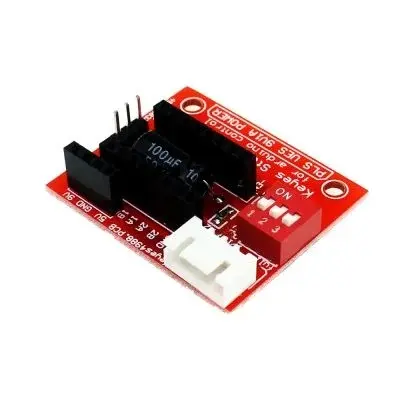
Stepper Motor Driver A4988 DRV8825 Expansion Board
The A4988/DRV8825 Stepper Motor Control Extension Board is a compact and user-friendly module designed to simplify the control of stepper motors using only two digital I/O pins. Compatible with A4988 and DRV8825 drivers, it is ideal for CNC machines, 3D printers, and robotics projects. Featuring screwless terminals, DIP switch configuration, and dual power inputs, this module offers precise and flexible motor control in a small footprint.
Package Includes:
- 1 x A4988/DRV8825 Stepper Motor Control Extension Board
Features:
- Compatible with A4988 and DRV8825 Drivers: Direct plug-in support for both popular stepper drivers.
- Simple Control Interface: Requires only two digital I/O pins for step and direction control.
- Screwless PCB Terminals: Quick and secure wire connections without the need for tools.
- Built-in DIP Switch: Easily adjust micro-stepping modes—16-step for A4988, 32-step for DRV8825.
- Dual Power Inputs: Separate terminals for 5V logic and 9V–24V motor power.
- Compact Design: Small and lightweight, perfect for integration into various setups.
- Wide Voltage Range: Supports motor supply voltages from 9V to 24V.
Specifications:
- Compatible Drivers: A4988 / DRV8825
- Control Pins: 2 digital I/O (Step and Direction)
- Logic Power Input: 5V DC
- Motor Power Input: 9V–24V DC
- Micro-stepping: 16 steps (A4988) / 32 steps (DRV8825)
- Connector Type: Screwless PCB terminals
- Operating Current: Depends on the inserted driver module
- Board Dimensions: Compact and lightweight
Connection Guide:

- Connect Stepper Driver: Insert the A4988 or DRV8825 module into the board with correct orientation.
- Wire the Motor: Connect the stepper motor to the Jm terminal.
- Power Supply:
- Connect 5V DC to the Jv terminal for logic power.
- Connect 9V–24V DC to the motor power terminal.
- Control Pins: Connect Step, Dir, En, and GND to your microcontroller.
- Micro-stepping Mode: Use the DIP switch to set the desired micro-stepping configuration.
Features:
- Compatible with A4988 and DRV8825 Drivers: Direct plug-in support for both popular stepper drivers.
- Simple Control Interface: Requires only two digital I/O pins for step and direction control.
- Screwless PCB Terminals: Quick and secure wire connections without the need for tools.
- Built-in DIP Switch: Easily adjust micro-stepping modes—16-step for A4988, 32-step for DRV8825.
- Dual Power Inputs: Separate terminals for 5V logic and 9V–24V motor power.
- Compact Design: Small and lightweight, perfect for integration into various setups.
- Wide Voltage Range: Supports motor supply voltages from 9V to 24V.
Specifications:
- Compatible Drivers: A4988 / DRV8825
- Control Pins: 2 digital I/O (Step and Direction)
- Logic Power Input: 5V DC
- Motor Power Input: 9V–24V DC
- Micro-stepping: 16 steps (A4988) / 32 steps (DRV8825)
- Connector Type: Screwless PCB terminals
- Operating Current: Depends on the inserted driver module
- Board Dimensions: Compact and lightweight
Connection Guide:
- Connect Stepper Driver: Insert the A4988 or DRV8825 module into the board with correct orientation.
- Wire the Motor: Connect the stepper motor to the Jm terminal.
- Power Supply:
- Connect 5V DC to the Jv terminal for logic power.
- Connect 9V–24V DC to the motor power terminal.
- Control Pins: Connect Step, Dir, En, and GND to your microcontroller.
- Micro-stepping Mode: Use the DIP switch to set the desired micro-stepping configuration.