Features
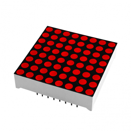
- 8x8 LED matrix: Contains 64 individual LEDs arranged in 8 rows and 8 columns.
- Red LED color: Provides clear red visual indication.
- Common-anode configuration: Rows share common anode connections while columns provide cathode connections.
- Character display: Suitable for displaying letters, numbers, and symbols.
- Pattern display: Can display icons, simple graphics, and custom pixel patterns.
- Multiplexing support: The matrix can be scanned rapidly by a microcontroller to control multiple LEDs using shared connections.
- Arduino compatible: Suitable for use with Arduino boards and other microcontrollers.
- Compact module: Suitable for breadboard prototyping and custom electronic projects.
Principle of Operation
The 8x8 LED matrix consists of 64 LEDs electrically arranged in a matrix of 8 rows and 8 columns. Instead of providing two separate connections for every LED, the LEDs share row and column connections, significantly reducing the number of required control lines.
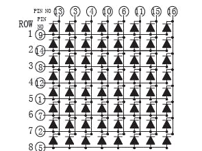
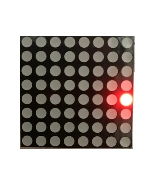
In the common-anode configuration, the anodes of LEDs in each row are connected together, while the cathodes are connected according to their respective columns. A microcontroller can select a row and control the corresponding column lines to illuminate specific LEDs. By rapidly scanning through the rows, multiple LEDs can appear illuminated simultaneously due to persistence of vision.
Applications
- Arduino LED matrix projects
- Character and number displays
- Simple graphic displays
- Scrolling text projects
- Icons and symbol displays
- LED animations
- Educational electronics projects
- Digital signs and indicators
- DIY clocks and counters
- Interactive electronic projects
Pinout
An 8x8 matrix uses 16 electrical connections, consisting of eight common anode row connections and eight cathode column connections. The exact physical pin numbering can vary depending on the specific LED matrix package, so the manufacturer's pin diagram should be checked before wiring.

| Connection Group | Quantity | Function |
|---|---|---|
| Common Anode Rows | 8 | Common positive connections for the LED rows |
| Cathode Columns | 8 | Negative connections for the LED columns |
Wiring
The LED matrix can be connected to an Arduino or another microcontroller using its row and column connections. Because the matrix requires multiple control lines, it is commonly driven using multiplexing or an external LED matrix driver.
Current-limiting resistors are required when driving the individual LED segments. For larger displays or applications requiring higher LED current, an appropriate transistor or dedicated LED driver should be used rather than driving all LED current directly from microcontroller GPIO pins.
_sjOU7T8mkS.png)
| Matrix Connection | Controller | Function |
|---|---|---|
| 8 Anode Rows | Digital output / driver | Select LED rows |
| 8 Cathode Columns | Digital output / driver | Select LEDs within the active row |
Code:
// Pins connect as per define
// Fill in the pins you used on your own setup.

#define ROW_1 2
#define ROW_2 3
#define ROW_3 4
#define ROW_4 5
#define ROW_5 6
#define ROW_6 7
#define ROW_7 8
#define ROW_8 9

#define COL_1 10
#define COL_2 11
#define COL_3 12
#define COL_4 13
#define COL_5 A0
#define COL_6 A1
#define COL_7 A2
#define COL_8 A3

const byte rows[] = {
    ROW_1, ROW_2, ROW_3, ROW_4, ROW_5, ROW_6, ROW_7, ROW_8
};

// The display buffer
// It shows a walking steps (1 = ON, 0 = OFF)
byte star1[] = {B00000110,B11000010,B10100100,B00011000,B00011000,B00100101,B01000011,B01100000};
byte star2[] = {B00110000,B00100000,B00100111,B00011001,B10011000,B11100100,B00000100,B00001100};
byte star3[] = {B00000110,B10001000,B10010000,B01011100,B00111010,B00001001,B00010001,B01100000};

float timeCount = 0;

void setup() {
    // Open serial port
    Serial.begin(9600);

    // Set all used pins to OUTPUT
    // This is very important! If the pins are set to input
    for (byte i = 2; i <= 13; i++)
        pinMode(i, OUTPUT);
    pinMode(A0, OUTPUT);
    pinMode(A1, OUTPUT);
    pinMode(A2, OUTPUT);
    pinMode(A3, OUTPUT);
}

void loop() {
  // This could be rewritten to not use a delay, which would make it appear brighter
delay(5);
timeCount += 1;
if(timeCount <  20) {
drawScreen(star1);
} else if (timeCount <  80) {
drawScreen(star2);
} else if (timeCount <  100) {
drawScreen(star3);
} else if (timeCount <  120) {
drawScreen(star1);
} else if (timeCount <  140) {
drawScreen(star2);
} else if (timeCount <  160) {
drawScreen(star3);
} else {
// back to the start
timeCount = 0;
}
}
 void  drawScreen(byte buffer2[]){


   // Turn on each row in series
    for (byte i = 0; i < 8; i++) {
        setColumns(buffer2[i]); // Set columns for this specific row

        digitalWrite(rows[i], HIGH);
        delay(2); // Set this to 50 or 100 if you want to see the multiplexing effect!
        digitalWrite(rows[i], LOW);

    }
}


void setColumns(byte b) {
    digitalWrite(COL_1, (~b >> 0) & 0x01); // Get the 1st bit: 10000000
    digitalWrite(COL_2, (~b >> 1) & 0x01); // Get the 2nd bit: 01000000
    digitalWrite(COL_3, (~b >> 2) & 0x01); // Get the 3rd bit: 00100000
    digitalWrite(COL_4, (~b >> 3) & 0x01); // Get the 4th bit: 00010000
    digitalWrite(COL_5, (~b >> 4) & 0x01); // Get the 5th bit: 00001000
    digitalWrite(COL_6, (~b >> 5) & 0x01); // Get the 6th bit: 00000100
    digitalWrite(COL_7, (~b >> 6) & 0x01); // Get the 7th bit: 00000010
    digitalWrite(COL_8, (~b >> 7) & 0x01); // Get the 8th bit: 00000001

    // If the polarity of your matrix is the opposite of mine
    // remove all the '~' above.
}
Specifications
| Product Type | 8x8 LED Matrix Display |
|---|---|
| LED Color | Red |
| Matrix Size | 8 × 8 |
| Number of LEDs | 64 |
| Configuration | Common Anode |
| Row Connections | 8 Common Anode Rows |
| Column Connections | 8 Cathode Columns |
| Total Connections | 16 |
| Dimensions | Approximately 60 × 60 mm |
| Interface | Direct row/column control |
Features
- 8x8 LED matrix: Contains 64 individual LEDs arranged in 8 rows and 8 columns.
- Red LED color: Provides clear red visual indication.
- Common-anode configuration: Rows share common anode connections while columns provide cathode connections.
- Character display: Suitable for displaying letters, numbers, and symbols.
- Pattern display: Can display icons, simple graphics, and custom pixel patterns.
- Multiplexing support: The matrix can be scanned rapidly by a microcontroller to control multiple LEDs using shared connections.
- Arduino compatible: Suitable for use with Arduino boards and other microcontrollers.
- Compact module: Suitable for breadboard prototyping and custom electronic projects.
Principle of Operation
The 8x8 LED matrix consists of 64 LEDs electrically arranged in a matrix of 8 rows and 8 columns. Instead of providing two separate connections for every LED, the LEDs share row and column connections, significantly reducing the number of required control lines.
In the common-anode configuration, the anodes of LEDs in each row are connected together, while the cathodes are connected according to their respective columns. A microcontroller can select a row and control the corresponding column lines to illuminate specific LEDs. By rapidly scanning through the rows, multiple LEDs can appear illuminated simultaneously due to persistence of vision.
Applications
- Arduino LED matrix projects
- Character and number displays
- Simple graphic displays
- Scrolling text projects
- Icons and symbol displays
- LED animations
- Educational electronics projects
- Digital signs and indicators
- DIY clocks and counters
- Interactive electronic projects
Pinout
An 8x8 matrix uses 16 electrical connections, consisting of eight common anode row connections and eight cathode column connections. The exact physical pin numbering can vary depending on the specific LED matrix package, so the manufacturer's pin diagram should be checked before wiring.
| Connection Group | Quantity | Function |
|---|---|---|
| Common Anode Rows | 8 | Common positive connections for the LED rows |
| Cathode Columns | 8 | Negative connections for the LED columns |
Wiring
The LED matrix can be connected to an Arduino or another microcontroller using its row and column connections. Because the matrix requires multiple control lines, it is commonly driven using multiplexing or an external LED matrix driver.
Current-limiting resistors are required when driving the individual LED segments. For larger displays or applications requiring higher LED current, an appropriate transistor or dedicated LED driver should be used rather than driving all LED current directly from microcontroller GPIO pins.
| Matrix Connection | Controller | Function |
|---|---|---|
| 8 Anode Rows | Digital output / driver | Select LED rows |
| 8 Cathode Columns | Digital output / driver | Select LEDs within the active row |
Code:
// Pins connect as per define
// Fill in the pins you used on your own setup.

#define ROW_1 2
#define ROW_2 3
#define ROW_3 4
#define ROW_4 5
#define ROW_5 6
#define ROW_6 7
#define ROW_7 8
#define ROW_8 9

#define COL_1 10
#define COL_2 11
#define COL_3 12
#define COL_4 13
#define COL_5 A0
#define COL_6 A1
#define COL_7 A2
#define COL_8 A3

const byte rows[] = {
    ROW_1, ROW_2, ROW_3, ROW_4, ROW_5, ROW_6, ROW_7, ROW_8
};

// The display buffer
// It shows a walking steps (1 = ON, 0 = OFF)
byte star1[] = {B00000110,B11000010,B10100100,B00011000,B00011000,B00100101,B01000011,B01100000};
byte star2[] = {B00110000,B00100000,B00100111,B00011001,B10011000,B11100100,B00000100,B00001100};
byte star3[] = {B00000110,B10001000,B10010000,B01011100,B00111010,B00001001,B00010001,B01100000};

float timeCount = 0;

void setup() {
    // Open serial port
    Serial.begin(9600);

    // Set all used pins to OUTPUT
    // This is very important! If the pins are set to input
    for (byte i = 2; i <= 13; i++)
        pinMode(i, OUTPUT);
    pinMode(A0, OUTPUT);
    pinMode(A1, OUTPUT);
    pinMode(A2, OUTPUT);
    pinMode(A3, OUTPUT);
}

void loop() {
  // This could be rewritten to not use a delay, which would make it appear brighter
delay(5);
timeCount += 1;
if(timeCount <  20) {
drawScreen(star1);
} else if (timeCount <  80) {
drawScreen(star2);
} else if (timeCount <  100) {
drawScreen(star3);
} else if (timeCount <  120) {
drawScreen(star1);
} else if (timeCount <  140) {
drawScreen(star2);
} else if (timeCount <  160) {
drawScreen(star3);
} else {
// back to the start
timeCount = 0;
}
}
 void  drawScreen(byte buffer2[]){


   // Turn on each row in series
    for (byte i = 0; i < 8; i++) {
        setColumns(buffer2[i]); // Set columns for this specific row

        digitalWrite(rows[i], HIGH);
        delay(2); // Set this to 50 or 100 if you want to see the multiplexing effect!
        digitalWrite(rows[i], LOW);

    }
}


void setColumns(byte b) {
    digitalWrite(COL_1, (~b >> 0) & 0x01); // Get the 1st bit: 10000000
    digitalWrite(COL_2, (~b >> 1) & 0x01); // Get the 2nd bit: 01000000
    digitalWrite(COL_3, (~b >> 2) & 0x01); // Get the 3rd bit: 00100000
    digitalWrite(COL_4, (~b >> 3) & 0x01); // Get the 4th bit: 00010000
    digitalWrite(COL_5, (~b >> 4) & 0x01); // Get the 5th bit: 00001000
    digitalWrite(COL_6, (~b >> 5) & 0x01); // Get the 6th bit: 00000100
    digitalWrite(COL_7, (~b >> 6) & 0x01); // Get the 7th bit: 00000010
    digitalWrite(COL_8, (~b >> 7) & 0x01); // Get the 8th bit: 00000001

    // If the polarity of your matrix is the opposite of mine
    // remove all the '~' above.
}
Specifications
| Product Type | 8x8 LED Matrix Display |
|---|---|
| LED Color | Red |
| Matrix Size | 8 × 8 |
| Number of LEDs | 64 |
| Configuration | Common Anode |
| Row Connections | 8 Common Anode Rows |
| Column Connections | 8 Cathode Columns |
| Total Connections | 16 |
| Dimensions | Approximately 60 × 60 mm |
| Interface | Direct row/column control |