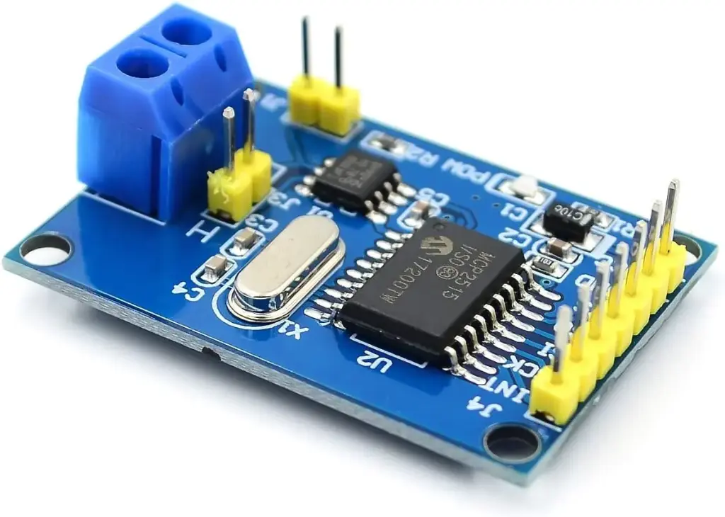
CAN Bus MCP2515 Module
The MCP2515 is a standalone Controller Area Network (CAN) controller module that enables the communication between multiple devices in industrial and automotive applications. It supports the transmission and reception of standard and extended data and remote frames and is connected to the Arduino board using Serial Peripheral Interface (SPI) communication. The module uses the TJA1050 interface for differential transmit and receive capabilities, and supports CAN operation speeds up to 1 Mbps. It features a high-speed CAN transceiver, 8MHZ crystal oscillator, 120Ω terminal resistance, independent key, LED indicator, and low current standby operation. The MCP2515 is commonly used as an add-on module for Arduino boards to enable CAN communication.
Package Includes:
- 1 x CAN Bus MCP2515 Module
Features:
- The module can be used as a stand-alone CAN controller or as an add-on module for microcontrollers such as Arduino boards.
- The CAN protocol is widely used in industrial and automotive applications to allow multiple devices to communicate with each other.
- The ability to support standard and extended data and remote frames provides flexibility in the type of data that can be transmitted and received.
- The SPI communication interface enables easy integration into existing projects, and the high-speed CAN transceiver allows for reliable data transmission over long distances.
- The 8 MHz crystal oscillator provides precise timing for data transmission and reception, and the 120Ω terminal resistance is required for proper termination of the CAN bus.
- The independent key, LED indicator, and power indicator make it easy to reset and monitor the module's status, and the low current standby operation reduces power consumption when the module is not actively transmitting or receiving data.
- The support for expanding multi-CAN bus interfaces allows for easy expansion of the CAN network, and the ability to connect up to 112 nodes in a network allows for large-scale communication between multiple devices in industrial and automotive applications.
Description:
The MCP2515 module is a standalone Controller Area Network (CAN) controller that provides a flexible and reliable communication solution for industrial and automotive applications. It is commonly used as an add-on module for microcontrollers such as Arduino boards. The module supports CAN specification Version 2.0B, which is a widely used protocol for communication between multiple devices in various applications. It supports the transmission and reception of both standard and extended data and remote frames, providing flexibility in the type of data that can be transmitted and received between devices. The module uses Serial Peripheral Interface (SPI) communication to connect to Arduino boards or other microcontrollers. The MCP2515 module uses a high-speed CAN transceiver TJA1050 for differential transmit and receive capabilities, which allows for reliable data transmission over long distances. The MCP2515 module can support CAN operation speeds up to 1 Mbps, which makes it suitable for a wide range of applications. It includes an 8 MHz crystal oscillator that provides precise timing for data transmission and reception. The module includes a 120Ω terminal resistance that is required for proper termination of the CAN bus. It also includes an independent key that can be used to reset the module, LED indicators that show the module's status and a power indicator that shows when the module is powered on. The MCP2515 module includes a low current standby mode, which reduces power consumption when the module is not actively transmitting or receiving data. It also supports expanding multi-CAN bus interfaces, which allows for easy expansion of the CAN network. The module can connect up to 112 nodes in a network, which allows for large-scale communication between multiple devices in industrial and automotive applications.
Principle of Work:
The Controller Area Network (CAN) protocol is a message-based communication protocol commonly used in industrial and automotive applications. The protocol is designed to provide reliable and efficient communication between multiple devices over a single bus, and it uses a variety of principles to achieve this.
Some of the key principles of the CAN protocol include:
- Message-Based Communication: The CAN protocol is message-based, which means that each device on the bus can send and receive messages to and from other devices. Messages are transmitted in the form of frames, which can be standard or extended depending on the type of data being transmitted.
- Arbitration: The CAN protocol uses a unique arbitration scheme to ensure that messages are transmitted in the correct order and without interference. Each message on the bus is assigned a priority level, and messages with higher priority are given priority over messages with lower priority.
- Error Detection and Correction: The CAN protocol uses several mechanisms to detect and correct errors that may occur during data transmission. These mechanisms include cyclic redundancy check (CRC), bit stuffing, and acknowledgments.
- Frame-Based Structure: The CAN protocol uses a specific frame-based structure for transmitting messages on the bus. Each frame includes a unique identifier, a data field, and several control bits that are used to manage the transmission and reception of the message.
- Bus Topology: The CAN protocol uses a bus topology, which means that all devices on the bus are connected to the same two wires (CAN High and CAN Low). This makes it easy to connect multiple devices to the same bus and allows for easy expansion of the network.
The MCP2515 module is a CAN controller that implements the CAN protocol and provides a flexible and reliable communication solution for industrial and automotive applications. The module is designed to work with microcontrollers such as Arduino boards and uses Serial Peripheral Interface (SPI) communication to connect to the microcontroller. To use the MCP2515 module in a project, you would typically connect it to an Arduino board using SPI communication and configure the module using the Arduino programming language. The module can be used to send and receive data between multiple devices on the CAN bus, allowing for real-time communication and control. For example, you could use the MCP2515 module in a project to control multiple motors or sensors in an industrial application. The module could be used to send commands to the motors or sensors over the CAN bus and receive feedback from them in real time.
Pinout of the Module:
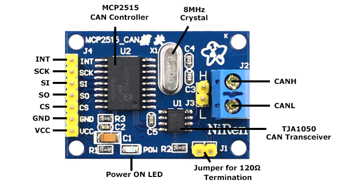
- MCP2515 CAN Controller: The MCP2515 is the primary component of the module, responsible for transmitting and receiving CAN messages. It is a standalone CAN controller that supports the CAN 2.0B specification and communicates with the host microcontroller via SPI.
- TJA1050 CAN Transceiver: The TJA1050 is a high-speed CAN transceiver that converts the digital signals from the MCP2515 into differential signals suitable for transmission over the CAN bus. It provides differential transmit and receive capability to the bus and features a low-current standby mode.
- Crystal Oscillator: The MCP2515 module typically features an 8MHz crystal oscillator, which provides a precise clock signal to the MCP2515 and ensures reliable communication over the CAN bus.
- Terminal Resistance: CAN bus networks require a 120Ω termination resistor to ensure proper signal quality and impedance matching. Some MCP2515 modules feature a built-in termination resistor, while others require an external resistor.
- Power and Status Indicators: Many MCP2515 modules feature LEDs to indicate power status and CAN bus activity. This can be helpful for debugging and troubleshooting, as well as monitoring the overall status of the system.
- Header Pins: The MCP2515 module typically features six header pins, which are used to connect the module to the host microcontroller via SPI. The pins include GND, VCC, CS, SI (SDI), SO (SDO), and SCK.
| Pin | Name | Function |
|---|---|---|
| 1 | INT | interrupt |
| 2 | GND | Ground |
| 3 | VCC | Power Supply (3.3V or 5V) |
| 4 | CS | Chip Select (active low) |
| 5 | SI (SDI) | SPI Data Input |
| 6 | SO (SDO) | SPI Data Output |
| 7 | SCK | SPI Clock Input |
Applications:
- Motor control: The TIP120 can be used to control the speed and direction of DC motors. By varying the current to the motor through the transistor, the speed and direction can be controlled.
- Relay control: The TIP120 can be used to control the activation of relays. By connecting the relay coil to the collector and the emitter, the TIP120 can be used to switch the relay on and off.
- LED control: The TIP120 can be used to control the brightness of LEDs. By varying the current to the LED through the transistor, the brightness can be controlled.
- Audio amplification: The TIP120 can be used as an audio amplifier. By controlling the current through the transistor with an audio signal, the signal can be amplified and output through a speaker.
- Power switching: The TIP120 can be used to switch high-power devices on and off. By controlling the current through the transistor, it can be used to switch power to devices such as heaters, pumps, and solenoids.
Circuit:
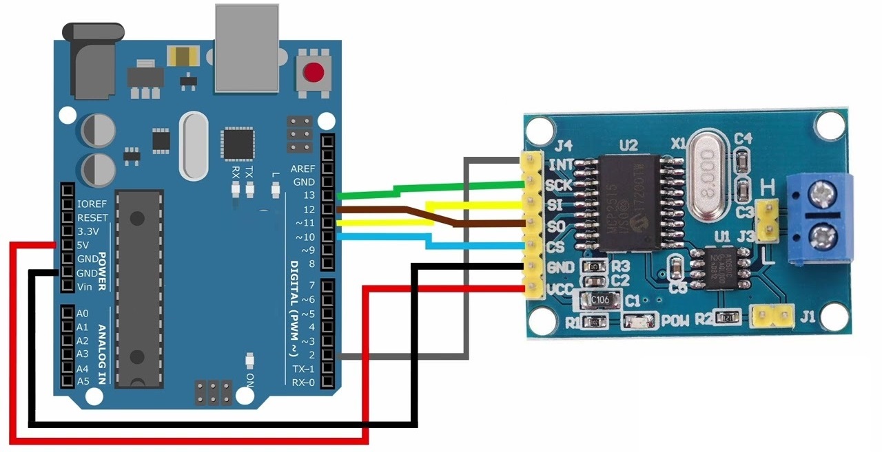
To connect an MCP2515 module to an Arduino Uno, you can use the following pin connections:
- MCP2515 CS pin to Arduino Uno pin 10
- MCP2515 INT pin to Arduino Uno pin 2
- MCP2515 SCK pin to Arduino Uno pin 13
- MCP2515 SO pin to Arduino Uno pin 12
- MCP2515 SI pin to Arduino Uno pin 11
- MCP2515 VCC pin to Arduino Uno 5V pin
- MCP2515 GND pin to Arduino Uno GND pin
Make sure to connect the MCP2515 module to the Arduino Uno while both devices are powered off, and only then power on both devices. This will prevent any potential damage to the devices.
Library:
To use the MCP_CAN library in your Arduino code, follow these steps:
- Download the MCP_CAN library from GitHub (https://github.com/coryjfowler/MCP_CAN_lib) as a ZIP file.
- Open the Arduino IDE and go to Sketch > Include Library > Add .ZIP Library.
- Navigate to the downloaded ZIP file and select it.
- The library will now be installed and ready to use in your code.
Code:
In this code, the MCP2515 module is initialized on pin 10 using the MCP_CAN library. The module is set to normal mode, and the interrupt pin is set to input. In the loop, the code checks if the interrupt pin is high, indicating that a message has been received on the CAN bus. If a message is available, the code reads the message and prints the ID and data to the serial monitor. The code also listens for input from the serial monitor. If the input starts with "send:", the code parses the message ID and data from the input string and sends the message using the CAN.sendMsgBuf function. If the message is sent successfully, the code prints a success message to the serial monitor, otherwise, it prints a failure message.
#include "SPI.h"
#include "mcp_can.h"
const int MCP2515_CS_PIN = 10;
const int MCP2515_INT_PIN = 2;
MCP_CAN CAN(MCP2515_CS_PIN); // Initialize MCP2515 module on pin 10
void setup() {
 Serial.begin(9600);
 if(CAN.begin(MCP_ANY, CAN_500KBPS, MCP_8MHZ) == CAN_OK) {
 Serial.println("MCP2515 Initialized Successfully!");
 CAN.setMode(MCP_NORMAL); // Set the module to normal mode
 } else {
 Serial.println("MCP2515 Initialization Failed!");
 }
 pinMode(MCP2515_INT_PIN, INPUT);
}
void loop() {
 if(digitalRead(MCP2515_INT_PIN) == HIGH) { // If the MCP2515 module has received a message
 unsigned long msgId = 0;
 uint8_t len = 0;
 uint8_t buf[8];
 if(CAN.checkReceive() == CAN_MSGAVAIL) { // Check if there is a message available
 CAN.readMsgBuf(&msgId, &len, buf); // Read the message
 Serial.print("CAN Message Received: ID = 0x");
 Serial.print(msgId, HEX);
 Serial.print(", Data = ");
 for(int i=0; i < len; i++) {
 Serial.print(buf[i], HEX);
 Serial.print(" ");
 }
 Serial.println();
 }
 }
 if(Serial.available()) { // If there is data in the serial buffer
 String input = Serial.readStringUntil('\n'); // Read the input string
 if(input.startsWith("send:")) { // If the input is a "send" command
 unsigned long msgId = 0;
 uint8_t len = 0;
 uint8_t buf[8];
 // Parse the input string to get the message ID and data
 sscanf(input.substring(5).c_str(), "%lx %hhx %hhx %hhx %hhx %hhx %hhx %hhx %hhx", &msgId, &buf[0], &buf[1], &buf[2], &buf[3], &buf[4], &buf[5], &buf[6], &buf[7]);
 len = input.length() - 5;
 // Send the message
 if(CAN.sendMsgBuf(msgId, 0, len, buf) == CAN_OK) {
 Serial.println("CAN Message Sent Successfully!");
 } else {
 Serial.println("CAN Message Send Failed!");
 }
 }
 }
}
#includeand"mcp_can.h": These are header files that provide the necessary functions to communicate with the MCP2515 CAN controller over the SPI interface.const int MCP2515_CS_PIN = 10;andconst int MCP2515_INT_PIN = 2;: These define the pins that are connected to the chip select (CS) and interrupt (INT) pins of the MCP2515 CAN controller.MCP_CAN CAN(MCP2515_CS_PIN);: This creates an instance of the MCP_CAN class that is used to interact with the MCP2515 CAN controller.Serial.begin(9600);: This initializes the serial communication at a baud rate of 9600.if(CAN.begin(MCP_ANY, CAN_500KBPS, MCP_8MHZ) == CAN_OK): This initializes the MCP2515 CAN controller with a bit rate of 500 kbps and a clock speed of 8 MHz.CAN.setMode(MCP_NORMAL);: This sets the MCP2515 CAN controller to normal mode, which allows it to send and receive CAN messages.pinMode(MCP2515_INT_PIN, INPUT);: This sets the interrupt pin of the MCP2515 CAN controller as an input pin.if(digitalRead(MCP2515_INT_PIN) == HIGH) {: This checks if the MCP2515 CAN controller has received a message by reading the state of the interrupt pin.if(CAN.checkReceive() == CAN_MSGAVAIL) {: This checks if there is a message available to be read from the MCP2515 CAN controller.CAN.readMsgBuf(&msgId, &len, buf);: This reads the message from the MCP2515 CAN controller into the variablesmsgId(message ID),len(message length), andbuf(message data).Serial.print("CAN Message Received: ID = 0x");,Serial.print(msgId, HEX);,Serial.print(", Data = ");, andSerial.print(buf[i], HEX);: These lines print out the received CAN message ID and data in hexadecimal format to the serial monitor.String input = Serial.readStringUntil('\n');: This reads a line of input from the serial monitor into the variableinput.if(input.startsWith("send:")) {: This checks if the input starts with the string "send:".sscanf(input.substring(5).c_str(), "%lx %hhx %hhx %hhx %hhx %hhx %hhx %hhx %hhx", &msgId, &buf[0], &buf[1], &buf[2], &buf[3], &buf[4], &buf[5], &buf[6], &buf[7]);: This parses the input string to extract the message ID and data bytes.len = input.length() - 5;: This calculates the message length based on the number of data bytes in the input string.if(CAN.sendMsgBuf(msgId, 0, len, buf) == CAN_OK) {: This sends the CAN message with the specified ID and data bytes using the MCP2515 CAN controller.Serial.println("CAN Message Sent Successfully!");andSerial.println("CAN Message Send Failed!");: These lines print out a message to the serial monitor indicating whether the CAN message was sent successfully or not.
Technical Details:
- Uses High-speed CAN transceiver TJA1050 or MCP2551
- Dimensions: varies depending on the module, but typically around 40mm x 25mm
- SPI control for expanding Multi CAN bus interface
- 8MHz crystal oscillator
- 120Ω terminal resistance
- Has an independent key, LED indicator, and Power indicator
- Supports up to 1 Mbps CAN operation
- Low current standby operation
- Up to 110 nodes can be connected
Resources:
Comparisons:
The MCP2515 CAN Bus module and the RobotDyn CAN-BUS Shield are both used for connecting Arduino to the CAN-BUS of a car or industrial equipment. However, the RobotDyn CAN-BUS Shield offers additional features such as a MicroSD-card reader, connectors for series I2C and serial UART, and connectors for GPS connection.
- In terms of the CAN-BUS interface, the MCP2515 uses a TJA1050 transceiver while the RobotDyn CAN-BUS Shield uses MCP2515 CAN-controller and MCP2551 CAN-transceiver circuits. The MCP2515 supports CAN V2.0B protocol with a speed of up to 1 Mb/s and offers SPI control, while the RobotDyn CAN-BUS Shield supports the same protocol and offers a higher SPI interface speed of 10 MHz.
- The MCP2515 module does not have a standard 9-terminal D-Sub connector for CAN connection, while the RobotDyn CAN-BUS Shield has both a standard 9-terminal D-Sub(male) connector and a 2-terminal block for fast connection of CANH and CANL wires. The RobotDyn CAN-BUS Shield also has LED data indications for CAN-BUS communication.
In the end, the RobotDyn CAN-BUS Shield offers more features and flexibility in connecting with other devices, while the MCP2515 module provides a simple and straightforward CAN-BUS interface.
Features:
- The module can be used as a stand-alone CAN controller or as an add-on module for microcontrollers such as Arduino boards.
- The CAN protocol is widely used in industrial and automotive applications to allow multiple devices to communicate with each other.
- The ability to support standard and extended data and remote frames provides flexibility in the type of data that can be transmitted and received.
- The SPI communication interface enables easy integration into existing projects, and the high-speed CAN transceiver allows for reliable data transmission over long distances.
- The 8 MHz crystal oscillator provides precise timing for data transmission and reception, and the 120Ω terminal resistance is required for proper termination of the CAN bus.
- The independent key, LED indicator, and power indicator make it easy to reset and monitor the module's status, and the low current standby operation reduces power consumption when the module is not actively transmitting or receiving data.
- The support for expanding multi-CAN bus interfaces allows for easy expansion of the CAN network, and the ability to connect up to 112 nodes in a network allows for large-scale communication between multiple devices in industrial and automotive applications.
Description:
The MCP2515 module is a standalone Controller Area Network (CAN) controller that provides a flexible and reliable communication solution for industrial and automotive applications. It is commonly used as an add-on module for microcontrollers such as Arduino boards. The module supports CAN specification Version 2.0B, which is a widely used protocol for communication between multiple devices in various applications. It supports the transmission and reception of both standard and extended data and remote frames, providing flexibility in the type of data that can be transmitted and received between devices. The module uses Serial Peripheral Interface (SPI) communication to connect to Arduino boards or other microcontrollers. The MCP2515 module uses a high-speed CAN transceiver TJA1050 for differential transmit and receive capabilities, which allows for reliable data transmission over long distances. The MCP2515 module can support CAN operation speeds up to 1 Mbps, which makes it suitable for a wide range of applications. It includes an 8 MHz crystal oscillator that provides precise timing for data transmission and reception. The module includes a 120Ω terminal resistance that is required for proper termination of the CAN bus. It also includes an independent key that can be used to reset the module, LED indicators that show the module's status and a power indicator that shows when the module is powered on. The MCP2515 module includes a low current standby mode, which reduces power consumption when the module is not actively transmitting or receiving data. It also supports expanding multi-CAN bus interfaces, which allows for easy expansion of the CAN network. The module can connect up to 112 nodes in a network, which allows for large-scale communication between multiple devices in industrial and automotive applications.
Principle of Work:
The Controller Area Network (CAN) protocol is a message-based communication protocol commonly used in industrial and automotive applications. The protocol is designed to provide reliable and efficient communication between multiple devices over a single bus, and it uses a variety of principles to achieve this.
Some of the key principles of the CAN protocol include:
- Message-Based Communication: The CAN protocol is message-based, which means that each device on the bus can send and receive messages to and from other devices. Messages are transmitted in the form of frames, which can be standard or extended depending on the type of data being transmitted.
- Arbitration: The CAN protocol uses a unique arbitration scheme to ensure that messages are transmitted in the correct order and without interference. Each message on the bus is assigned a priority level, and messages with higher priority are given priority over messages with lower priority.
- Error Detection and Correction: The CAN protocol uses several mechanisms to detect and correct errors that may occur during data transmission. These mechanisms include cyclic redundancy check (CRC), bit stuffing, and acknowledgments.
- Frame-Based Structure: The CAN protocol uses a specific frame-based structure for transmitting messages on the bus. Each frame includes a unique identifier, a data field, and several control bits that are used to manage the transmission and reception of the message.
- Bus Topology: The CAN protocol uses a bus topology, which means that all devices on the bus are connected to the same two wires (CAN High and CAN Low). This makes it easy to connect multiple devices to the same bus and allows for easy expansion of the network.
The MCP2515 module is a CAN controller that implements the CAN protocol and provides a flexible and reliable communication solution for industrial and automotive applications. The module is designed to work with microcontrollers such as Arduino boards and uses Serial Peripheral Interface (SPI) communication to connect to the microcontroller. To use the MCP2515 module in a project, you would typically connect it to an Arduino board using SPI communication and configure the module using the Arduino programming language. The module can be used to send and receive data between multiple devices on the CAN bus, allowing for real-time communication and control. For example, you could use the MCP2515 module in a project to control multiple motors or sensors in an industrial application. The module could be used to send commands to the motors or sensors over the CAN bus and receive feedback from them in real time.
Pinout of the Module:
- MCP2515 CAN Controller: The MCP2515 is the primary component of the module, responsible for transmitting and receiving CAN messages. It is a standalone CAN controller that supports the CAN 2.0B specification and communicates with the host microcontroller via SPI.
- TJA1050 CAN Transceiver: The TJA1050 is a high-speed CAN transceiver that converts the digital signals from the MCP2515 into differential signals suitable for transmission over the CAN bus. It provides differential transmit and receive capability to the bus and features a low-current standby mode.
- Crystal Oscillator: The MCP2515 module typically features an 8MHz crystal oscillator, which provides a precise clock signal to the MCP2515 and ensures reliable communication over the CAN bus.
- Terminal Resistance: CAN bus networks require a 120Ω termination resistor to ensure proper signal quality and impedance matching. Some MCP2515 modules feature a built-in termination resistor, while others require an external resistor.
- Power and Status Indicators: Many MCP2515 modules feature LEDs to indicate power status and CAN bus activity. This can be helpful for debugging and troubleshooting, as well as monitoring the overall status of the system.
- Header Pins: The MCP2515 module typically features six header pins, which are used to connect the module to the host microcontroller via SPI. The pins include GND, VCC, CS, SI (SDI), SO (SDO), and SCK.
| Pin | Name | Function |
|---|---|---|
| 1 | INT | interrupt |
| 2 | GND | Ground |
| 3 | VCC | Power Supply (3.3V or 5V) |
| 4 | CS | Chip Select (active low) |
| 5 | SI (SDI) | SPI Data Input |
| 6 | SO (SDO) | SPI Data Output |
| 7 | SCK | SPI Clock Input |
Applications:
- Motor control: The TIP120 can be used to control the speed and direction of DC motors. By varying the current to the motor through the transistor, the speed and direction can be controlled.
- Relay control: The TIP120 can be used to control the activation of relays. By connecting the relay coil to the collector and the emitter, the TIP120 can be used to switch the relay on and off.
- LED control: The TIP120 can be used to control the brightness of LEDs. By varying the current to the LED through the transistor, the brightness can be controlled.
- Audio amplification: The TIP120 can be used as an audio amplifier. By controlling the current through the transistor with an audio signal, the signal can be amplified and output through a speaker.
- Power switching: The TIP120 can be used to switch high-power devices on and off. By controlling the current through the transistor, it can be used to switch power to devices such as heaters, pumps, and solenoids.
Circuit:
To connect an MCP2515 module to an Arduino Uno, you can use the following pin connections:
- MCP2515 CS pin to Arduino Uno pin 10
- MCP2515 INT pin to Arduino Uno pin 2
- MCP2515 SCK pin to Arduino Uno pin 13
- MCP2515 SO pin to Arduino Uno pin 12
- MCP2515 SI pin to Arduino Uno pin 11
- MCP2515 VCC pin to Arduino Uno 5V pin
- MCP2515 GND pin to Arduino Uno GND pin
Make sure to connect the MCP2515 module to the Arduino Uno while both devices are powered off, and only then power on both devices. This will prevent any potential damage to the devices.
Library:
To use the MCP_CAN library in your Arduino code, follow these steps:
- Download the MCP_CAN library from GitHub (https://github.com/coryjfowler/MCP_CAN_lib) as a ZIP file.
- Open the Arduino IDE and go to Sketch > Include Library > Add .ZIP Library.
- Navigate to the downloaded ZIP file and select it.
- The library will now be installed and ready to use in your code.
Code:
In this code, the MCP2515 module is initialized on pin 10 using the MCP_CAN library. The module is set to normal mode, and the interrupt pin is set to input. In the loop, the code checks if the interrupt pin is high, indicating that a message has been received on the CAN bus. If a message is available, the code reads the message and prints the ID and data to the serial monitor. The code also listens for input from the serial monitor. If the input starts with "send:", the code parses the message ID and data from the input string and sends the message using the CAN.sendMsgBuf function. If the message is sent successfully, the code prints a success message to the serial monitor, otherwise, it prints a failure message.
#include "SPI.h"
#include "mcp_can.h"
const int MCP2515_CS_PIN = 10;
const int MCP2515_INT_PIN = 2;
MCP_CAN CAN(MCP2515_CS_PIN); // Initialize MCP2515 module on pin 10
void setup() {
 Serial.begin(9600);
 if(CAN.begin(MCP_ANY, CAN_500KBPS, MCP_8MHZ) == CAN_OK) {
 Serial.println("MCP2515 Initialized Successfully!");
 CAN.setMode(MCP_NORMAL); // Set the module to normal mode
 } else {
 Serial.println("MCP2515 Initialization Failed!");
 }
 pinMode(MCP2515_INT_PIN, INPUT);
}
void loop() {
 if(digitalRead(MCP2515_INT_PIN) == HIGH) { // If the MCP2515 module has received a message
 unsigned long msgId = 0;
 uint8_t len = 0;
 uint8_t buf[8];
 if(CAN.checkReceive() == CAN_MSGAVAIL) { // Check if there is a message available
 CAN.readMsgBuf(&msgId, &len, buf); // Read the message
 Serial.print("CAN Message Received: ID = 0x");
 Serial.print(msgId, HEX);
 Serial.print(", Data = ");
 for(int i=0; i < len; i++) {
 Serial.print(buf[i], HEX);
 Serial.print(" ");
 }
 Serial.println();
 }
 }
 if(Serial.available()) { // If there is data in the serial buffer
 String input = Serial.readStringUntil('\n'); // Read the input string
 if(input.startsWith("send:")) { // If the input is a "send" command
 unsigned long msgId = 0;
 uint8_t len = 0;
 uint8_t buf[8];
 // Parse the input string to get the message ID and data
 sscanf(input.substring(5).c_str(), "%lx %hhx %hhx %hhx %hhx %hhx %hhx %hhx %hhx", &msgId, &buf[0], &buf[1], &buf[2], &buf[3], &buf[4], &buf[5], &buf[6], &buf[7]);
 len = input.length() - 5;
 // Send the message
 if(CAN.sendMsgBuf(msgId, 0, len, buf) == CAN_OK) {
 Serial.println("CAN Message Sent Successfully!");
 } else {
 Serial.println("CAN Message Send Failed!");
 }
 }
 }
}
#includeand"mcp_can.h": These are header files that provide the necessary functions to communicate with the MCP2515 CAN controller over the SPI interface.const int MCP2515_CS_PIN = 10;andconst int MCP2515_INT_PIN = 2;: These define the pins that are connected to the chip select (CS) and interrupt (INT) pins of the MCP2515 CAN controller.MCP_CAN CAN(MCP2515_CS_PIN);: This creates an instance of the MCP_CAN class that is used to interact with the MCP2515 CAN controller.Serial.begin(9600);: This initializes the serial communication at a baud rate of 9600.if(CAN.begin(MCP_ANY, CAN_500KBPS, MCP_8MHZ) == CAN_OK): This initializes the MCP2515 CAN controller with a bit rate of 500 kbps and a clock speed of 8 MHz.CAN.setMode(MCP_NORMAL);: This sets the MCP2515 CAN controller to normal mode, which allows it to send and receive CAN messages.pinMode(MCP2515_INT_PIN, INPUT);: This sets the interrupt pin of the MCP2515 CAN controller as an input pin.if(digitalRead(MCP2515_INT_PIN) == HIGH) {: This checks if the MCP2515 CAN controller has received a message by reading the state of the interrupt pin.if(CAN.checkReceive() == CAN_MSGAVAIL) {: This checks if there is a message available to be read from the MCP2515 CAN controller.CAN.readMsgBuf(&msgId, &len, buf);: This reads the message from the MCP2515 CAN controller into the variablesmsgId(message ID),len(message length), andbuf(message data).Serial.print("CAN Message Received: ID = 0x");,Serial.print(msgId, HEX);,Serial.print(", Data = ");, andSerial.print(buf[i], HEX);: These lines print out the received CAN message ID and data in hexadecimal format to the serial monitor.String input = Serial.readStringUntil('\n');: This reads a line of input from the serial monitor into the variableinput.if(input.startsWith("send:")) {: This checks if the input starts with the string "send:".sscanf(input.substring(5).c_str(), "%lx %hhx %hhx %hhx %hhx %hhx %hhx %hhx %hhx", &msgId, &buf[0], &buf[1], &buf[2], &buf[3], &buf[4], &buf[5], &buf[6], &buf[7]);: This parses the input string to extract the message ID and data bytes.len = input.length() - 5;: This calculates the message length based on the number of data bytes in the input string.if(CAN.sendMsgBuf(msgId, 0, len, buf) == CAN_OK) {: This sends the CAN message with the specified ID and data bytes using the MCP2515 CAN controller.Serial.println("CAN Message Sent Successfully!");andSerial.println("CAN Message Send Failed!");: These lines print out a message to the serial monitor indicating whether the CAN message was sent successfully or not.
Technical Details:
- Uses High-speed CAN transceiver TJA1050 or MCP2551
- Dimensions: varies depending on the module, but typically around 40mm x 25mm
- SPI control for expanding Multi CAN bus interface
- 8MHz crystal oscillator
- 120Ω terminal resistance
- Has an independent key, LED indicator, and Power indicator
- Supports up to 1 Mbps CAN operation
- Low current standby operation
- Up to 110 nodes can be connected
Resources:
Comparisons:
The MCP2515 CAN Bus module and the RobotDyn CAN-BUS Shield are both used for connecting Arduino to the CAN-BUS of a car or industrial equipment. However, the RobotDyn CAN-BUS Shield offers additional features such as a MicroSD-card reader, connectors for series I2C and serial UART, and connectors for GPS connection.
- In terms of the CAN-BUS interface, the MCP2515 uses a TJA1050 transceiver while the RobotDyn CAN-BUS Shield uses MCP2515 CAN-controller and MCP2551 CAN-transceiver circuits. The MCP2515 supports CAN V2.0B protocol with a speed of up to 1 Mb/s and offers SPI control, while the RobotDyn CAN-BUS Shield supports the same protocol and offers a higher SPI interface speed of 10 MHz.
- The MCP2515 module does not have a standard 9-terminal D-Sub connector for CAN connection, while the RobotDyn CAN-BUS Shield has both a standard 9-terminal D-Sub(male) connector and a 2-terminal block for fast connection of CANH and CANL wires. The RobotDyn CAN-BUS Shield also has LED data indications for CAN-BUS communication.
In the end, the RobotDyn CAN-BUS Shield offers more features and flexibility in connecting with other devices, while the MCP2515 module provides a simple and straightforward CAN-BUS interface.