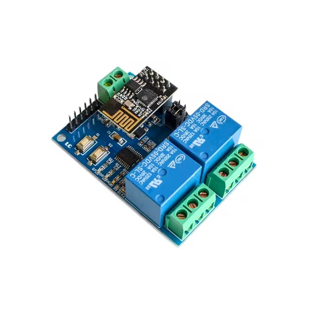
ESP8266 ESP-01 WIFI Wireless with 2CH Relay Module Board
The Dual WiFi Relay Module is an advanced control solution built on the ESP-01 WiFi module and powered by the STM8S103 high-performance microprocessor. It enables seamless wireless control of a dual-channel relay via a mobile application, requiring only minimal setup within a local area network (LAN). Ideal for home automation, industrial control, and other IoT applications.
Package Contents
- 1 x Dual-channel WiFi Relay Module
Features
- Integrated Components:
- Equipped with ESP-01 WiFi module for reliable wireless communication.
- Powered by STM8S103 microcontroller for stable and efficient operation.
- Dual Operating Modes:
- Mode 1: Direct phone-to-module connection (AP mode).
- Mode 2: Router-based connection (STA mode) for extended range.
- Can also act as a USB relay when ESP-01 is removed.
- Impressive Transmission Distance:
- Mode 1: Up to 100 meters in open space.
- Mode 2: Range depends on router signal strength.
- Smart Configuration: SmartConfig technology for easy setup and credential saving.
- Durable Relay Design: 5V 10A 250V AC (or 10A 30V DC) with diode protection and 100k+ cycles.
- User-Friendly Board: Status indicators, jumpers, UART & SWIM interfaces for development.
Specifications
- Model: ESP8266 (ESP-01)
- Channels: 2 (Dual-channel)
- Board Size: 59 x 40 mm
- Weight: Approx. 36g
- Power Supply: 5V input
Pinout

| Pin/Port | Description |
|---|---|
| IN+, IN- | 5V power input |
| 5V, GND, SWIM, NRST | STM8S program download port |
| TX, RX | UART serial communication |
| Button S1 | Switch between Mode 1 & Mode 2 |
| Button S2 | Restore factory settings |
| LED D7 (Red) | Mode 1 indicator |
| LED D5 (Blue) | Mode 2 indicator |
| LED D6 (Green) | Working condition (off / 0.5s / 2s flash / solid) |
| LED D28 & D4 (Red) | Relay ON indicator lights |
| 2 Jumper Caps | RX ↔ RX1 and TX ↔ TX1 (normal use), debugging (top position) |
| COM1, COM2 | Common relay terminals |
| NO1, NO2 | Normally open terminals |
| NC1, NC2 | Normally closed terminals |
Relay Control Instructions (HEX)
- Turn ON Relay 1:
A0 01 01 A2 - Turn OFF Relay 1:
A0 01 00 A1 - Turn ON Relay 2:
A0 02 01 A3 - Turn OFF Relay 2:
A0 02 00 A2
Setup Requirements
- 5V/1A Power Adapter
- ESP Touch-Demo App (WiFi configuration)
- EasyTCP-20 App (relay control)
Setup Steps
- Connect Power: IN+ to +5V, IN- to GND.
- WiFi Setup (Mode 2): Use "ESP Touch-Demo" to enter WiFi SSID and password.
- Relay Control: Use "EasyTCP-20" to send HEX commands.
Operating Modes
Mode 1: Direct AP Connection
- Insert ESP-01 and power the module. Green LED blinks every 2 seconds after ~4 seconds.
- Connect phone to ESP-01 hotspot.
- Open "EasyTCP-20", click "CONNECT", then send HEX commands to toggle relays.
Mode 2: Router-Based Communication
- Insert ESP-01, power the module, and press S1. Blue LED lights up and starts 0.5s blinking.
- Connect phone to router and run "ESP Touch-Demo". Enter WiFi password and confirm.
- App shows IP address (e.g., 192.168.0.189) when configured.
- Open "EasyTCP-20", enter IP, click "CONNECT", then send HEX commands.
Additional Notes
- First-time WiFi setup takes ~1 minute; reconnection ~20 seconds.
- Press S2 or power cycle to reset WiFi settings.
- If the router signal is weak, the green LED goes off and reconnects automatically.
- TCP disconnects after 6 minutes of inactivity. Reconnect via "CONNECT" button.
- Only when the green LED blinks every 2s or is steady can the buttons be used.
Features
- Integrated Components:
- Equipped with ESP-01 WiFi module for reliable wireless communication.
- Powered by STM8S103 microcontroller for stable and efficient operation.
- Dual Operating Modes:
- Mode 1: Direct phone-to-module connection (AP mode).
- Mode 2: Router-based connection (STA mode) for extended range.
- Can also act as a USB relay when ESP-01 is removed.
- Impressive Transmission Distance:
- Mode 1: Up to 100 meters in open space.
- Mode 2: Range depends on router signal strength.
- Smart Configuration: SmartConfig technology for easy setup and credential saving.
- Durable Relay Design: 5V 10A 250V AC (or 10A 30V DC) with diode protection and 100k+ cycles.
- User-Friendly Board: Status indicators, jumpers, UART & SWIM interfaces for development.
Specifications
- Model: ESP8266 (ESP-01)
- Channels: 2 (Dual-channel)
- Board Size: 59 x 40 mm
- Weight: Approx. 36g
- Power Supply: 5V input
Pinout
| Pin/Port | Description |
|---|---|
| IN+, IN- | 5V power input |
| 5V, GND, SWIM, NRST | STM8S program download port |
| TX, RX | UART serial communication |
| Button S1 | Switch between Mode 1 & Mode 2 |
| Button S2 | Restore factory settings |
| LED D7 (Red) | Mode 1 indicator |
| LED D5 (Blue) | Mode 2 indicator |
| LED D6 (Green) | Working condition (off / 0.5s / 2s flash / solid) |
| LED D28 & D4 (Red) | Relay ON indicator lights |
| 2 Jumper Caps | RX ↔ RX1 and TX ↔ TX1 (normal use), debugging (top position) |
| COM1, COM2 | Common relay terminals |
| NO1, NO2 | Normally open terminals |
| NC1, NC2 | Normally closed terminals |
Relay Control Instructions (HEX)
- Turn ON Relay 1:
A0 01 01 A2 - Turn OFF Relay 1:
A0 01 00 A1 - Turn ON Relay 2:
A0 02 01 A3 - Turn OFF Relay 2:
A0 02 00 A2
Setup Requirements
- 5V/1A Power Adapter
- ESP Touch-Demo App (WiFi configuration)
- EasyTCP-20 App (relay control)
Setup Steps
- Connect Power: IN+ to +5V, IN- to GND.
- WiFi Setup (Mode 2): Use "ESP Touch-Demo" to enter WiFi SSID and password.
- Relay Control: Use "EasyTCP-20" to send HEX commands.
Operating Modes
Mode 1: Direct AP Connection
- Insert ESP-01 and power the module. Green LED blinks every 2 seconds after ~4 seconds.
- Connect phone to ESP-01 hotspot.
- Open "EasyTCP-20", click "CONNECT", then send HEX commands to toggle relays.
Mode 2: Router-Based Communication
- Insert ESP-01, power the module, and press S1. Blue LED lights up and starts 0.5s blinking.
- Connect phone to router and run "ESP Touch-Demo". Enter WiFi password and confirm.
- App shows IP address (e.g., 192.168.0.189) when configured.
- Open "EasyTCP-20", enter IP, click "CONNECT", then send HEX commands.
Additional Notes
- First-time WiFi setup takes ~1 minute; reconnection ~20 seconds.
- Press S2 or power cycle to reset WiFi settings.
- If the router signal is weak, the green LED goes off and reconnects automatically.
- TCP disconnects after 6 minutes of inactivity. Reconnect via "CONNECT" button.
- Only when the green LED blinks every 2s or is steady can the buttons be used.