- All products
- Development Boards
- ESP8266
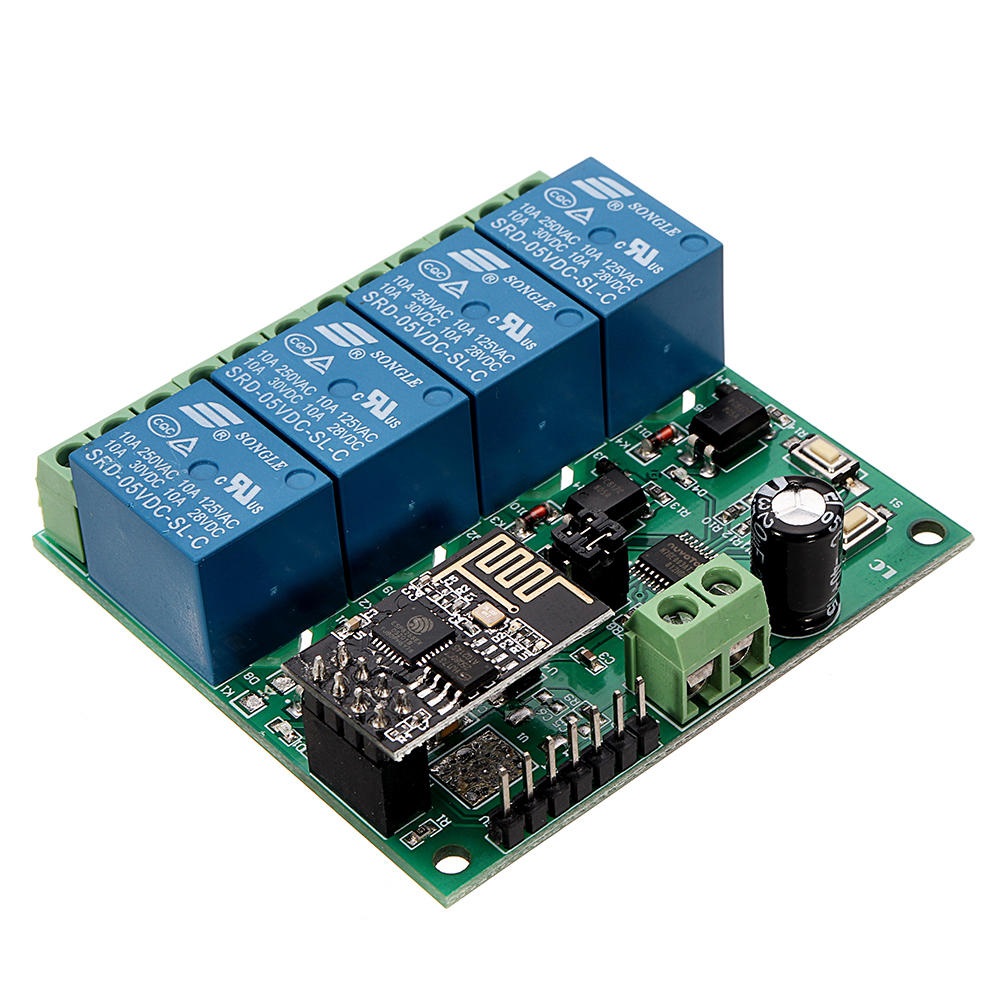
- ESP8266 ESP-01 WIFI Wireless with 4CH Relay Module Board
- ESP8266
Features
- Onboard ESP-01 WiFi module and high-performance STM8S103 microprocessor.
- 2 Working Modes:
- Mode 1: Mobile phone connects directly to the WiFi module (AP mode).
- Mode 2: Mobile phone and WiFi module connected to the same router (STA mode).
- Additional Function: Can act as a USB relay when ESP-01 is removed.
- Transmission Distance:
- Mode 1: Up to 100 meters in open environments.
- Mode 2: Dependent on router signal strength.
- Uses SmartConfig for app-based WiFi configuration and saves credentials.
- Built-in 5V 10A 250V AC relay (or 10A 30V DC), tested for over 100,000 cycles.
- Diode discharge protection and fast response time.
- Board includes mode selection button and real-time status LED indicators.
- Includes UART debugging and SWIM programming interface.
Specifications
- Product Name: DC 5V ESP8266 WiFi 4-Channel Relay Module
- Working Voltage: DC 5V
- Load Voltage: DC 30V 10A / AC 250V 10A
- Operating Temperature: -40℃ ~ 85℃
- Humidity: 0% ~ 95% RH
- Size: 63 × 60 × 20 mm
Setup Instructions
- Connect 5V/1A power to IN+ and IN- on the module.
- Install the Android app ESP Touch-Demo to configure WiFi credentials (Mode 2).
- Install EasyTCP-20 app to send relay control commands in HEX format via TCP.
Work Mode 1 (Direct Connection)
- Power the module; green LED will slow-flash (every 2s) after ~4s.
- Connect your phone to the ESP-01 WiFi hotspot (AP).
- Open EasyTCP-20, click "CONNECT". Use IP
192.168.4.1and port8080. - Once connected, green LED stays on. Send HEX instructions via the gray squares.
Work Mode 2 (Router Connection)
- Short press S1 after boot to enter Mode 2. Blue LED turns on, green LED blinks every 0.5s.
- Open ESP Touch-Demo app, enter router WiFi password, click "Confirm".
- After successful setup, app will show ESP8266 IP (e.g.,
192.168.0.174), which is saved for future use. - Open EasyTCP-20, input ESP8266 IP and port
8080, click "CONNECT". - Green LED will stop blinking and remain on after successful connection.
Additional Features – USB Relay Mode
- Remove the ESP-01 module.
- Connect a USB-to-TTL converter to the module.
- Select Mode 1. Open UART debugging software (e.g., SSCOM32).
- Set Baud rate to 115200 and send HEX commands to control the relay.
Important Notes
- First WiFi setup may take ~1 minute; future reboots will auto-connect in ~20s.
- To reset WiFi settings, press S2 or power cycle the board.
- If the router signal is weak or lost, green LED turns off. Reconnect is automatic.
- Buttons only respond when green LED is flashing every 2s or steady on.
- If no data is sent for 6+ minutes, TCP disconnects. Click "CONNECT" again in EasyTCP-20.
- Relay is a switch only – it does not output voltage directly.
- Please refer to the user manual before operation.