Skip to Content

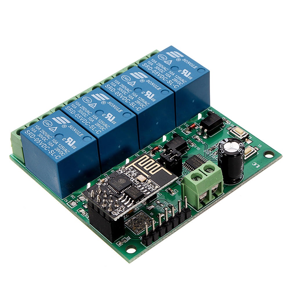
ESP8266 ESP-01 WIFI Wireless with 4CH Relay Module Board

The Dual WiFi Relay Module is based on the ESP-01 WiFi module. With a simple setup, it enables wireless control of four relays using a mobile app via LAN. This versatile module supports two operation modes and is suitable for home automation and IoT applications.

Package Contents

  • 1 × 4-Channel WiFi Relay Module

55.00 AED 55.00 AED Tax Included
55.00 AED Tax Included

Not Available For Sale

This combination does not exist.

Wifi Relay

Terms and Conditions
30-day money-back guarantee
Shipping: 2-3 Business Days


Features

  • Onboard ESP-01 WiFi module and high-performance STM8S103 microprocessor.
  • 2 Working Modes:
    • Mode 1: Mobile phone connects directly to the WiFi module (AP mode).
    • Mode 2: Mobile phone and WiFi module connected to the same router (STA mode).
  • Additional Function: Can act as a USB relay when ESP-01 is removed.
  • Transmission Distance:
    • Mode 1: Up to 100 meters in open environments.
    • Mode 2: Dependent on router signal strength.
  • Uses SmartConfig for app-based WiFi configuration and saves credentials.
  • Built-in 5V 10A 250V AC relay (or 10A 30V DC), tested for over 100,000 cycles.
  • Diode discharge protection and fast response time.
  • Board includes mode selection button and real-time status LED indicators.
  • Includes UART debugging and SWIM programming interface.

Specifications

  • Product Name: DC 5V ESP8266 WiFi 4-Channel Relay Module
  • Working Voltage: DC 5V
  • Load Voltage: DC 30V 10A / AC 250V 10A
  • Operating Temperature: -40℃ ~ 85℃
  • Humidity: 0% ~ 95% RH
  • Size: 63 × 60 × 20 mm

Setup Instructions

  1. Connect 5V/1A power to IN+ and IN- on the module.
  2. Install the Android app ESP Touch-Demo to configure WiFi credentials (Mode 2).
  3. Install EasyTCP-20 app to send relay control commands in HEX format via TCP.

Work Mode 1 (Direct Connection)

  1. Power the module; green LED will slow-flash (every 2s) after ~4s.
  2. Connect your phone to the ESP-01 WiFi hotspot (AP).
  3. Open EasyTCP-20, click "CONNECT". Use IP 192.168.4.1 and port 8080.
  4. Once connected, green LED stays on. Send HEX instructions via the gray squares.

Work Mode 2 (Router Connection)

  1. Short press S1 after boot to enter Mode 2. Blue LED turns on, green LED blinks every 0.5s.
  2. Open ESP Touch-Demo app, enter router WiFi password, click "Confirm".
  3. After successful setup, app will show ESP8266 IP (e.g., 192.168.0.174), which is saved for future use.
  4. Open EasyTCP-20, input ESP8266 IP and port 8080, click "CONNECT".
  5. Green LED will stop blinking and remain on after successful connection.

Additional Features – USB Relay Mode

  1. Remove the ESP-01 module.
  2. Connect a USB-to-TTL converter to the module.
  3. Select Mode 1. Open UART debugging software (e.g., SSCOM32).
  4. Set Baud rate to 115200 and send HEX commands to control the relay.

Important Notes

  • First WiFi setup may take ~1 minute; future reboots will auto-connect in ~20s.
  • To reset WiFi settings, press S2 or power cycle the board.
  • If the router signal is weak or lost, green LED turns off. Reconnect is automatic.
  • Buttons only respond when green LED is flashing every 2s or steady on.
  • If no data is sent for 6+ minutes, TCP disconnects. Click "CONNECT" again in EasyTCP-20.
  • Relay is a switch only – it does not output voltage directly.
  • Please refer to the user manual before operation.