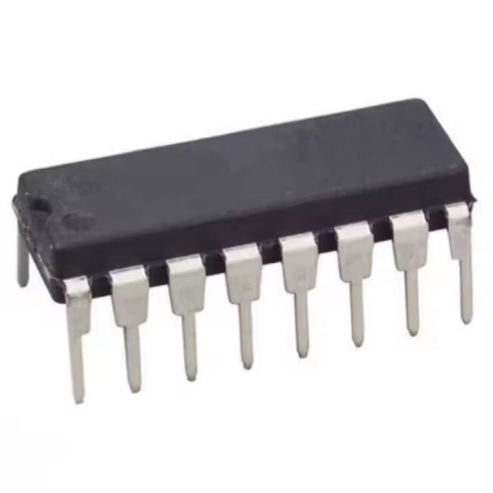
Specifications:
- Synchronous or asynchronous preset
- Operates at medium speed with a clock frequency (fCL) = 3.6 MHz at VDD = 10V
- Can be cascaded for designing more than an 8-bit counter
- Maximum value of input current at 18V = 1 µA
- Wide voltage supply range of 3 to 15V with different noise margins according to temperature
- One output can drive up to 50 inputs
- Inputs are provided with diode protection for interfacing inputs to voltages (with current limiting resistors when Vcc is in excess)
- Standardized, symmetrical output characteristics
- Parametric ratings: 5V, 12V, and 15V
Pinout of the CD40103:
It has 16 pins in total. The table below lists all pins along with their functions:
| Pin Name |
Description |
| CLOCK |
Enabling and Disabling of the clock signal. |
| CLEAR |
Clear the counter to its maximum count. |
| CARRY-IN / COUNTER ENABLE |
Carry-input pin, also known as counter enable. When HIGH, the counter stops counting. |
| J0 – J7 |
Jam inputs representing an 8-bit binary word. |
| VDD |
Positive terminal of power supply. |
| VSS |
Ground terminal. |
| CARRY-OUT / ZERO-DETECT |
Output pin that goes LOW for one complete clock cycle if carry-in input is active low. |
| SYNCHRONOUS PRESET-ENABLE |
Preset the counter synchronously. |
| ASYNCHRONOUS PRESET-ENABLE |
Preset the counter asynchronously. |
How CD40103 Down Counter Can Be Used?
On every positive edge of a clock signal, the value in the counter decrements by one. The counter is reset to its maximum value of 255 (decimal) when the CLEAR input is low. It has two preset enable options:
- Synchronous preset-enable: When active low, data available on pins J0–J7 is loaded into the counter at the next positive clock edge.
- Asynchronous preset-enable: When active low, data from JAM inputs is loaded into the counter asynchronously, regardless of the clock, carry-input, or synchronous preset-enable pin state.
