?unique=a15ba4e)
Arduino Uno SMD Rev3 (Original)
The UNO is the most known and used development board. This is the UNO R3 SMD, which copies everything in the DIP Arduino Uno and makes use of the ATmega16U2 to communicate with the PC.
Package Includes:
- 1 x UNO R3 SMD Original
Features:
-
ATmega328 processor running at 16MHz
-
Atmega-16U2 Serial to USB converter
-
32KB Flash memory
-
14 Digital I/O pins
-
6 PWM pins shared with digital I/O
-
6 Analog inputs that can also be used as digital I/O (up to 20 digital I/O in total)
-
1 Hardware serial port
-
5V Operation
Description:
The UNO R3 SMD is a development board that mimics everything in the classic Arduino Uno. It uses the ATmega16U2 to communicate with the PC and upload sketches. The board supports an extensive range of shields, allowing easy expansion of your project's functionality. The pin headers on the Uno board let you easily connect everything using Dupont wires, ensuring a hassle-free setup for your projects.
Principle of Work:
Arduino Uno is open hardware, meaning its blueprints and specifications are available for anyone to copy. This openness allows individuals or businesses to design their own boards, which work seamlessly with the Arduino framework. Additionally, Arduino provides open software, enabling users to develop and modify their own applications. The Uno board works with the Arduino IDE (Integrated Development Environment), which is used to write and upload code (sketches) via an onboard Serial Converter and an embedded bootloader, eliminating the need for an external programmer. You can use various libraries to program a wide range of sensors and modules, making it easier to interface with devices without needing to understand the technical details.
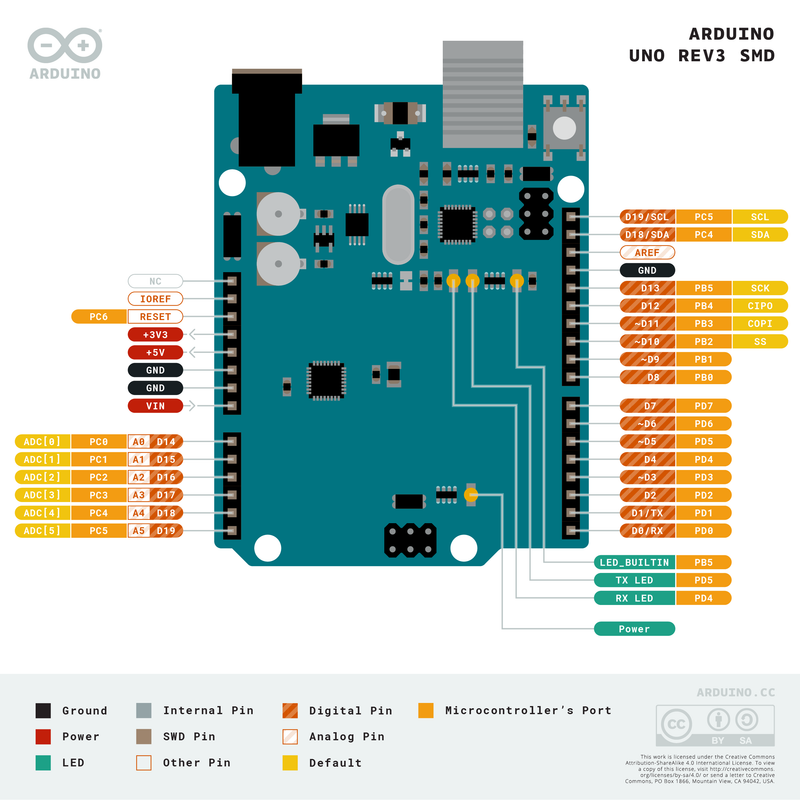
Pinout of the Module:
-
Serial Communication Pin: Connects to serial communication (4 pins: GND, VCC, RX, TX).
-
Ground: Ground pins.
-
V Pins (VCC): Powers external sensors and modules. Voltage (3.3V or 5V) is selected via a slide switch.
-
Digital I/O: 14 digital I/O pins (D0 to D13), with 6 supporting PWM. These pins can be used for both input and output operations, such as controlling LEDs or relays.
-
AREF: Used for analog reference voltage.
-
SDA & SCL: I2C communication pins.
-
ICSP Header: In-Circuit Serial Programming (ICSP) header for AVR programming.
-
Microcontroller: ATMEGA328P-AU.
-
D13 LED: Built-in LED on digital pin 13 (ON when HIGH, OFF when LOW).
-
TX/RX LEDs: TX LED flashes when transmitting data, RX LED flashes when receiving data.
-
Power LED: Indicates the board is powered on.
-
USB Connection: Powers the board and uploads programs via USB.
-
ATMEGA 16U2-MU: USB to serial chip for communication.
-
Voltage Regulator: Converts external DC voltage (7-12V) to 5V to power the board.
-
DC Power Jack: Accepts external DC power (7-12V).
-
RESET Header: Connect an external button for resetting the board.
-
Pin 3V3 Output: Provides 3.3V output.
-
Pin 5V Output: Provides 5V output.
-
Vin: External voltage input (7-12V).
Applications:
-
Weighing Machines
-
Traffic Light Countdown Timer
-
Parking Lot Counter
-
Embedded Systems
-
Home Automation
-
Industrial Automation
-
Medical Instruments
-
Emergency Light for Railways
Circuit:
No additional circuit is required. This example uses the built-in LED on pin 13.
Connecting with Arduino First Time:
-
Open Arduino IDE:
-
Download and install the Arduino IDE from the official website.
-
-
Connect the Board to Your Computer:
-
Use a data USB cable to connect the Arduino board to your computer (ensure it’s a data cable, not a charge-only one).
-
-
Select Board:
-
In the Arduino IDE, go to Tools > Board, and select the correct board.
-
-
Select Port:
-
Go to Tools > Port and select the port where your board is connected.
-
-
Upload a Sketch:
-
Write or open a sketch (e.g., Blink), click Upload, and the sketch will run on the board.
-
Code Example:
void setup() {
  pinMode(13, 1);
}

void loop() {
  digitalWrite(13, 1);
  delay(1000);
  digitalWrite(13, 0);
  delay(1000);
}
Technical Details:
| Microcontroller | ATmega328P |
|---|---|
| Operating Voltage | 5V |
| Input Voltage (Recommended) | 7-12V |
| Input Voltage (Limit) | 6-20V |
| DC Current per I/O Pin | 20 mA |
| DC Current for 3.3V Pin | 50 mA |
| Clock Speed | 16 MHz |
| LED_BUILTIN | 13 |
| Length | 68.6 mm |
| Width | 53.4 mm |
| Weight | 25 g |
Resources:
Comparisons:
The Arduino UNO R3 SMD is very similar to the Arduino UNO SMD Clone. However, the clone uses the CH340 chip, which requires a third-party driver, while the original uses the ATmega16U2 for USB-to-serial conversion, which doesn't need additional drivers. The original board is known for its superior build quality and aesthetic design, while the clone offers more flexibility with dual pin headers for both male and female connections.
Features:
-
ATmega328 processor running at 16MHz
-
Atmega-16U2 Serial to USB converter
-
32KB Flash memory
-
14 Digital I/O pins
-
6 PWM pins shared with digital I/O
-
6 Analog inputs that can also be used as digital I/O (up to 20 digital I/O in total)
-
1 Hardware serial port
-
5V Operation
Description:
The UNO R3 SMD is a development board that mimics everything in the classic Arduino Uno. It uses the ATmega16U2 to communicate with the PC and upload sketches. The board supports an extensive range of shields, allowing easy expansion of your project's functionality. The pin headers on the Uno board let you easily connect everything using Dupont wires, ensuring a hassle-free setup for your projects.
Principle of Work:
Arduino Uno is open hardware, meaning its blueprints and specifications are available for anyone to copy. This openness allows individuals or businesses to design their own boards, which work seamlessly with the Arduino framework. Additionally, Arduino provides open software, enabling users to develop and modify their own applications. The Uno board works with the Arduino IDE (Integrated Development Environment), which is used to write and upload code (sketches) via an onboard Serial Converter and an embedded bootloader, eliminating the need for an external programmer. You can use various libraries to program a wide range of sensors and modules, making it easier to interface with devices without needing to understand the technical details.
Pinout of the Module:
-
Serial Communication Pin: Connects to serial communication (4 pins: GND, VCC, RX, TX).
-
Ground: Ground pins.
-
V Pins (VCC): Powers external sensors and modules. Voltage (3.3V or 5V) is selected via a slide switch.
-
Digital I/O: 14 digital I/O pins (D0 to D13), with 6 supporting PWM. These pins can be used for both input and output operations, such as controlling LEDs or relays.
-
AREF: Used for analog reference voltage.
-
SDA & SCL: I2C communication pins.
-
ICSP Header: In-Circuit Serial Programming (ICSP) header for AVR programming.
-
Microcontroller: ATMEGA328P-AU.
-
D13 LED: Built-in LED on digital pin 13 (ON when HIGH, OFF when LOW).
-
TX/RX LEDs: TX LED flashes when transmitting data, RX LED flashes when receiving data.
-
Power LED: Indicates the board is powered on.
-
USB Connection: Powers the board and uploads programs via USB.
-
ATMEGA 16U2-MU: USB to serial chip for communication.
-
Voltage Regulator: Converts external DC voltage (7-12V) to 5V to power the board.
-
DC Power Jack: Accepts external DC power (7-12V).
-
RESET Header: Connect an external button for resetting the board.
-
Pin 3V3 Output: Provides 3.3V output.
-
Pin 5V Output: Provides 5V output.
-
Vin: External voltage input (7-12V).
Applications:
-
Weighing Machines
-
Traffic Light Countdown Timer
-
Parking Lot Counter
-
Embedded Systems
-
Home Automation
-
Industrial Automation
-
Medical Instruments
-
Emergency Light for Railways
Circuit:
No additional circuit is required. This example uses the built-in LED on pin 13.
Connecting with Arduino First Time:
-
Open Arduino IDE:
-
Download and install the Arduino IDE from the official website.
-
-
Connect the Board to Your Computer:
-
Use a data USB cable to connect the Arduino board to your computer (ensure it’s a data cable, not a charge-only one).
-
-
Select Board:
-
In the Arduino IDE, go to Tools > Board, and select the correct board.
-
-
Select Port:
-
Go to Tools > Port and select the port where your board is connected.
-
-
Upload a Sketch:
-
Write or open a sketch (e.g., Blink), click Upload, and the sketch will run on the board.
-
Code Example:
void setup() {
  pinMode(13, 1);
}

void loop() {
  digitalWrite(13, 1);
  delay(1000);
  digitalWrite(13, 0);
  delay(1000);
}
Technical Details:
| Microcontroller | ATmega328P |
|---|---|
| Operating Voltage | 5V |
| Input Voltage (Recommended) | 7-12V |
| Input Voltage (Limit) | 6-20V |
| DC Current per I/O Pin | 20 mA |
| DC Current for 3.3V Pin | 50 mA |
| Clock Speed | 16 MHz |
| LED_BUILTIN | 13 |
| Length | 68.6 mm |
| Width | 53.4 mm |
| Weight | 25 g |
Resources:
Comparisons:
The Arduino UNO R3 SMD is very similar to the Arduino UNO SMD Clone. However, the clone uses the CH340 chip, which requires a third-party driver, while the original uses the ATmega16U2 for USB-to-serial conversion, which doesn't need additional drivers. The original board is known for its superior build quality and aesthetic design, while the clone offers more flexibility with dual pin headers for both male and female connections.