Features
- Powered by Raspberry Pi RP2040
- Processor: Dual-core Arm Cortex-M0+
- Internal RAM: 264KB
- Flash Memory: 2MB
- Specifications: Same as Raspberry Pi Pico
- Robot Controller Board
- Servo Motors: 4 ports
- DC Motors: 2 channels with quick test buttons
- Versatile Power Circuit
- Power Selection: Automatic between USB 5V, LiPo (1-cell), or Vin (3.6-6V)
- Battery Charger: Built-in 1-cell LiPo/Li-Ion charger with protection features
- Switch: Power on/off
- Additional Features
- Status LEDs: 13 for GPIO pins
- Buzzer: 1x Piezo with mute switch
- Buttons: 2x push buttons
- RGB LEDs: 2x (Neopixel)
- Grove Ports: 7x flexible I/O options (digital, analog, I2C, SPI, UART)
- CircuitPython: Preloaded
- Mounting Holes: 4x 4.8mm (LEGO® pin compatible), 6x M3 screw holes
Specifications
- Microcontroller: Raspberry Pi RP2040
- Processor: Dual-core Arm Cortex-M0+
- RAM: 264KB
- Flash Memory: 2MB
- Motor Ports: 4x Servo, 2x DC
- Power Input: USB 5V, LiPo (1-cell), Vin (3.6-6V)
- Status LEDs: 13
- Piezo Buzzer: 1
- Push Buttons: 2
- RGB LEDs: 2
- Grove Ports: 7
- Mounting Holes: 4x 4.8mm, 6x M3
Applications
- DIY robotics projects
- Motion control applications
- Educational purposes in learning programming and electronics
- Prototyping and experimentation with the RP2040 microcontroller
Pinout
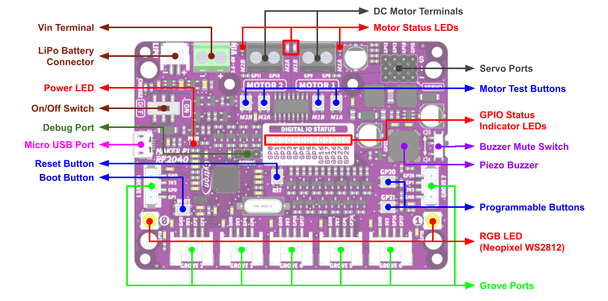
Function
| Function | Description |
|---|---|
| Vin Terminal | Connect to any power source within 3.6 - 6V. |
| LiPo Battery Connector | Connect to Single Cell LiPo / Li-Ion Battery. The battery is rechargeable via USB. The battery is protected from overcharged and over discharged. |
| Power LED | Turn on when powered up. |
| On/Off Switch | Turn on/off the power. |
| Debug Port | Debugging port of the RP2040. |
| Micro USB Port | Used for upload programs from PC. Can also be used to power up the board. |
| Reset Button | Press to reset the RP2040. |
| Boot Button | Enter bootloader mode when pressed and reset. Used to load Micropython/Circuitpython or custom firmware. |
Grove Ports
| Grove Port | GPIO | PWM | SPI | I2C | UART | Analog |
|---|---|---|---|---|---|---|
| 1 | 0 | PWM0-A | SDI0 | SDA0 | TX0 | - |
| 1 | - | PWM0-B | CSn0 | SCL0 | RX0 | - |
| 2 | 2 | PWM1-A | SCK0 | SDA1 | - | - |
| 3 | - | PWM1-B | SDO0 | SCL1 | - | - |
| 3 | 4 | PWM2-A | SDI0 | SDA0 | TX1 | - |
| 5 | - | PWM2-B | CSn0 | SCL0 | RX1 | - |
| 4 | 16 | PWM0-A | SDI0 | SDA0 | TX0 | - |
| 17 | - | PWM0-B | CSn0 | SCL0 | RX0 | - |
| 5 | 6 | PWM3-A | SCK0 | SDA1 | - | - |
| 26 | - | PWM5-A | - | SDA1 | - | ADC0 |
| 6 | 26 | PWM5-A | - | SDA1 | - | ADC0 |
| 27 | - | PWM5-B | - | SCL1 | - | ADC1 |
| 7 | 7 | PWM3-B | SDO0 | SCL1 | - | - |
| 28 | - | PWM6-A | - | - | - | ADC2 |
Other Features
- RGB LEDs (WS2812): User programmable WS2812B RGB LED, GP18
- Programmable Buttons: Connected to GP20, GP21
- Piezo Buzzer: Connected to GP22
- Buzzer Mute Switch: Mute control
- GPIO Status LEDs: Indicate GPIO states
- Motor Test Buttons: Test motor driver functionality
- Servo Ports: 4x RC servo motors (GP12–GP15)
- Motor Status LEDs: Show motor activity
- DC Motor Terminals: M1A (GP8), M1B (GP9), M2A (GP10), M2B (GP11)
Motor Driver Truth Table
| Input A (GP8 / GP10) | Input B (GP9 / GP11) | Output A (M1A / M2A) | Output B (M1B / M2B) | Motor |
|---|---|---|---|---|
| Low | Low | Low | Low | Brake |
| High | Low | High | Low | Forward |
| Low | High | Low | High | Backward |
| High | High | Hi-Z | Hi-Z | Coast |
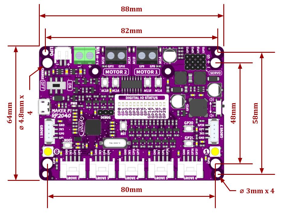
Dimension
Features
- Powered by Raspberry Pi RP2040
- Processor: Dual-core Arm Cortex-M0+
- Internal RAM: 264KB
- Flash Memory: 2MB
- Specifications: Same as Raspberry Pi Pico
- Robot Controller Board
- Servo Motors: 4 ports
- DC Motors: 2 channels with quick test buttons
- Versatile Power Circuit
- Power Selection: Automatic between USB 5V, LiPo (1-cell), or Vin (3.6-6V)
- Battery Charger: Built-in 1-cell LiPo/Li-Ion charger with protection features
- Switch: Power on/off
- Additional Features
- Status LEDs: 13 for GPIO pins
- Buzzer: 1x Piezo with mute switch
- Buttons: 2x push buttons
- RGB LEDs: 2x (Neopixel)
- Grove Ports: 7x flexible I/O options (digital, analog, I2C, SPI, UART)
- CircuitPython: Preloaded
- Mounting Holes: 4x 4.8mm (LEGO® pin compatible), 6x M3 screw holes
Specifications
- Microcontroller: Raspberry Pi RP2040
- Processor: Dual-core Arm Cortex-M0+
- RAM: 264KB
- Flash Memory: 2MB
- Motor Ports: 4x Servo, 2x DC
- Power Input: USB 5V, LiPo (1-cell), Vin (3.6-6V)
- Status LEDs: 13
- Piezo Buzzer: 1
- Push Buttons: 2
- RGB LEDs: 2
- Grove Ports: 7
- Mounting Holes: 4x 4.8mm, 6x M3
Applications
- DIY robotics projects
- Motion control applications
- Educational purposes in learning programming and electronics
- Prototyping and experimentation with the RP2040 microcontroller
Pinout
Function
| Function | Description |
|---|---|
| Vin Terminal | Connect to any power source within 3.6 - 6V. |
| LiPo Battery Connector | Connect to Single Cell LiPo / Li-Ion Battery. The battery is rechargeable via USB. The battery is protected from overcharged and over discharged. |
| Power LED | Turn on when powered up. |
| On/Off Switch | Turn on/off the power. |
| Debug Port | Debugging port of the RP2040. |
| Micro USB Port | Used for upload programs from PC. Can also be used to power up the board. |
| Reset Button | Press to reset the RP2040. |
| Boot Button | Enter bootloader mode when pressed and reset. Used to load Micropython/Circuitpython or custom firmware. |
Grove Ports
| Grove Port | GPIO | PWM | SPI | I2C | UART | Analog |
|---|---|---|---|---|---|---|
| 1 | 0 | PWM0-A | SDI0 | SDA0 | TX0 | - |
| 1 | - | PWM0-B | CSn0 | SCL0 | RX0 | - |
| 2 | 2 | PWM1-A | SCK0 | SDA1 | - | - |
| 3 | - | PWM1-B | SDO0 | SCL1 | - | - |
| 3 | 4 | PWM2-A | SDI0 | SDA0 | TX1 | - |
| 5 | - | PWM2-B | CSn0 | SCL0 | RX1 | - |
| 4 | 16 | PWM0-A | SDI0 | SDA0 | TX0 | - |
| 17 | - | PWM0-B | CSn0 | SCL0 | RX0 | - |
| 5 | 6 | PWM3-A | SCK0 | SDA1 | - | - |
| 26 | - | PWM5-A | - | SDA1 | - | ADC0 |
| 6 | 26 | PWM5-A | - | SDA1 | - | ADC0 |
| 27 | - | PWM5-B | - | SCL1 | - | ADC1 |
| 7 | 7 | PWM3-B | SDO0 | SCL1 | - | - |
| 28 | - | PWM6-A | - | - | - | ADC2 |
Other Features
- RGB LEDs (WS2812): User programmable WS2812B RGB LED, GP18
- Programmable Buttons: Connected to GP20, GP21
- Piezo Buzzer: Connected to GP22
- Buzzer Mute Switch: Mute control
- GPIO Status LEDs: Indicate GPIO states
- Motor Test Buttons: Test motor driver functionality
- Servo Ports: 4x RC servo motors (GP12–GP15)
- Motor Status LEDs: Show motor activity
- DC Motor Terminals: M1A (GP8), M1B (GP9), M2A (GP10), M2B (GP11)
Motor Driver Truth Table
| Input A (GP8 / GP10) | Input B (GP9 / GP11) | Output A (M1A / M2A) | Output B (M1B / M2B) | Motor |
|---|---|---|---|---|
| Low | Low | Low | Low | Brake |
| High | Low | High | Low | Forward |
| Low | High | Low | High | Backward |
| High | High | Hi-Z | Hi-Z | Coast |
Dimension