Features:
- 3-Axis Motion Detection: Measures acceleration simultaneously on X, Y, and Z axes.
- Multiple Measurement Ranges: Supports selectable ranges of ±2g, ±4g, ±8g, and ±16g.
- Multiple Communication Interfaces: Compatible with I2C, SPI, and ADC GPIO interfaces.
- Temperature Compensation: Allows correction of measurement variations caused by environmental temperature changes.
- Low Power Consumption: Optimized for portable and battery-powered applications.
- Wide Voltage Compatibility: Operates from both 3V and 5V systems.
- Grove Ecosystem Compatible: Plug-and-play connection through the standard Grove interface.
- Interrupt Support: Dedicated interrupt output for motion-triggered events.
Principle of Work:
The LIS3DHTR is a MEMS (Micro-Electro-Mechanical Systems) accelerometer that measures acceleration by detecting displacement of microscopic internal structures caused by movement or gravity.
- MEMS Sensing Element: Tiny suspended structures move when subjected to acceleration forces.
- Capacitance Measurement: Internal circuitry measures changes in capacitance caused by the movement of these structures.
- Digital Conversion: The sensor converts capacitance variations into digital acceleration values.
- Multi-Axis Processing: Independent sensing elements provide acceleration data for X, Y, and Z axes.
- Communication Interface: Data is transmitted to the host microcontroller through I2C or SPI.
Interaction with MCU (Microcontroller Unit):
- Power Connection: Connect the module to a 3V or 5V power source.
- Interface Selection: Use the Grove I2C connector for quick integration or configure SPI if required.
- Data Acquisition: The MCU reads acceleration registers through I2C or SPI communication.
- Motion Processing: Software interprets acceleration data to determine movement, tilt, vibration, or orientation.
- Interrupt Events: Motion or free-fall events can trigger hardware interrupts for efficient system response.
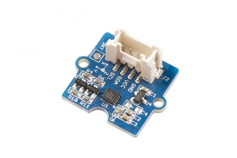
Pinout:

| Pin | Description |
|---|---|
| VCC | 3V/5V Power Supply |
| GND | Ground |
| SDA | I2C Data Line |
| SCL | I2C Clock Line |
| INT | Interrupt Output |
| CS | SPI Chip Select |
| SDO | SPI Data Output / I2C Address Selection |
Applications:
- Free-fall detection systems
- Motion sensing applications
- Pedometers and fitness trackers
- Gaming controllers and VR devices
- Robotics and autonomous navigation
- Vibration monitoring systems
- Industrial equipment monitoring
- Impact detection and event logging
- Orientation and tilt sensing
- Smart wearable devices
Circuit:
| Accelerometer Pin | Arduino UNO |
|---|---|
| VCC | 5V |
| GND | GND |
| SDA | A4 |
| SCL | A5 |
Library:
To simplify communication with the LIS3DHTR sensor, install the official Grove LIS3DHTR library from Seeed Studio.
Link
Code:
#include "LIS3DHTR.h"
#include <Wire.h>
LIS3DHTR<TwoWire> LIS;
void setup() {
Serial.begin(9600);
LIS.begin(Wire, 0x19);
if(!LIS) {
Serial.println("LIS3DHTR not found.");
while(1);
}
LIS.setOutputDataRate(LIS3DHTR_DATARATE_50HZ);
LIS.setFullScaleRange(LIS3DHTR_RANGE_2G);
}
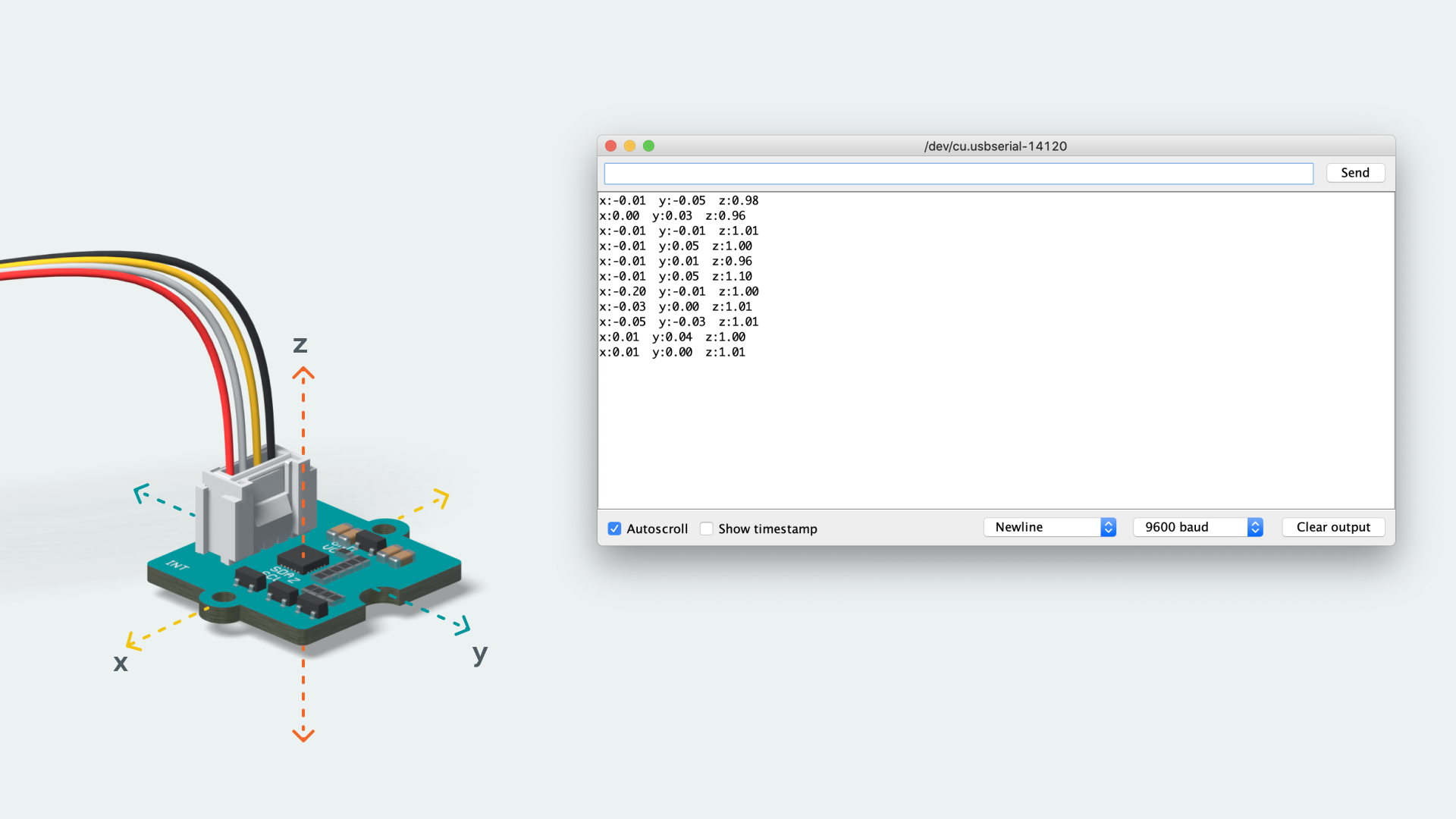
void loop() {
Serial.print("X: ");
Serial.print(LIS.getAccelerationX());
Serial.print(" Y: ");
Serial.print(LIS.getAccelerationY());
Serial.print(" Z: ");
Serial.println(LIS.getAccelerationZ());
delay(500);
}
Code Explanation:
- Initialization: Initializes I2C communication and the LIS3DHTR sensor.
- Device Detection: Verifies that the sensor is connected and responding.
- Configuration: Sets the output data rate and measurement range.
- Reading Data: Continuously retrieves acceleration values for X, Y, and Z axes.
- Output: Prints acceleration measurements to the Serial Monitor.
Technical Specifications:
- Sensor Chip: LIS3DHTR
- Measurement Axes: X, Y, Z
- Measurement Range: ±2g, ±4g, ±8g, ±16g
- Supply Voltage: 3V / 5V
- Communication Interfaces: I2C, SPI, GPIO ADC
- Default I2C Address: 0x19
- Alternative I2C Address: 0x18 (SDO connected to GND)
- ADC GPIO Input Range: 0 – 3.3V
- Interrupt Output: Supported
- Temperature Compensation: Supported
- Low Power Operation: Yes
Resources:
Features:
- 3-Axis Motion Detection: Measures acceleration simultaneously on X, Y, and Z axes.
- Multiple Measurement Ranges: Supports selectable ranges of ±2g, ±4g, ±8g, and ±16g.
- Multiple Communication Interfaces: Compatible with I2C, SPI, and ADC GPIO interfaces.
- Temperature Compensation: Allows correction of measurement variations caused by environmental temperature changes.
- Low Power Consumption: Optimized for portable and battery-powered applications.
- Wide Voltage Compatibility: Operates from both 3V and 5V systems.
- Grove Ecosystem Compatible: Plug-and-play connection through the standard Grove interface.
- Interrupt Support: Dedicated interrupt output for motion-triggered events.
Principle of Work:
The LIS3DHTR is a MEMS (Micro-Electro-Mechanical Systems) accelerometer that measures acceleration by detecting displacement of microscopic internal structures caused by movement or gravity.
- MEMS Sensing Element: Tiny suspended structures move when subjected to acceleration forces.
- Capacitance Measurement: Internal circuitry measures changes in capacitance caused by the movement of these structures.
- Digital Conversion: The sensor converts capacitance variations into digital acceleration values.
- Multi-Axis Processing: Independent sensing elements provide acceleration data for X, Y, and Z axes.
- Communication Interface: Data is transmitted to the host microcontroller through I2C or SPI.
Interaction with MCU (Microcontroller Unit):
- Power Connection: Connect the module to a 3V or 5V power source.
- Interface Selection: Use the Grove I2C connector for quick integration or configure SPI if required.
- Data Acquisition: The MCU reads acceleration registers through I2C or SPI communication.
- Motion Processing: Software interprets acceleration data to determine movement, tilt, vibration, or orientation.
- Interrupt Events: Motion or free-fall events can trigger hardware interrupts for efficient system response.
Pinout:
| Pin | Description |
|---|---|
| VCC | 3V/5V Power Supply |
| GND | Ground |
| SDA | I2C Data Line |
| SCL | I2C Clock Line |
| INT | Interrupt Output |
| CS | SPI Chip Select |
| SDO | SPI Data Output / I2C Address Selection |
Applications:
- Free-fall detection systems
- Motion sensing applications
- Pedometers and fitness trackers
- Gaming controllers and VR devices
- Robotics and autonomous navigation
- Vibration monitoring systems
- Industrial equipment monitoring
- Impact detection and event logging
- Orientation and tilt sensing
- Smart wearable devices
Circuit:
| Accelerometer Pin | Arduino UNO |
|---|---|
| VCC | 5V |
| GND | GND |
| SDA | A4 |
| SCL | A5 |
Library:
To simplify communication with the LIS3DHTR sensor, install the official Grove LIS3DHTR library from Seeed Studio.
Link
Code:
#include "LIS3DHTR.h"
#include <Wire.h>
LIS3DHTR<TwoWire> LIS;
void setup() {
 Serial.begin(9600);
 LIS.begin(Wire, 0x19);
 if(!LIS) {
 Serial.println("LIS3DHTR not found.");
 while(1);
 }
 LIS.setOutputDataRate(LIS3DHTR_DATARATE_50HZ);
 LIS.setFullScaleRange(LIS3DHTR_RANGE_2G);
}
void loop() {
 Serial.print("X: ");
 Serial.print(LIS.getAccelerationX());
 Serial.print(" Y: ");
 Serial.print(LIS.getAccelerationY());
 Serial.print(" Z: ");
 Serial.println(LIS.getAccelerationZ());
 delay(500);
}
Code Explanation:
- Initialization: Initializes I2C communication and the LIS3DHTR sensor.
- Device Detection: Verifies that the sensor is connected and responding.
- Configuration: Sets the output data rate and measurement range.
- Reading Data: Continuously retrieves acceleration values for X, Y, and Z axes.
- Output: Prints acceleration measurements to the Serial Monitor.
Technical Specifications:
- Sensor Chip: LIS3DHTR
- Measurement Axes: X, Y, Z
- Measurement Range: ±2g, ±4g, ±8g, ±16g
- Supply Voltage: 3V / 5V
- Communication Interfaces: I2C, SPI, GPIO ADC
- Default I2C Address: 0x19
- Alternative I2C Address: 0x18 (SDO connected to GND)
- ADC GPIO Input Range: 0 – 3.3V
- Interrupt Output: Supported
- Temperature Compensation: Supported
- Low Power Operation: Yes