Features:
- Increased memory: 32 kB SRAM and 256 kB flash memory, much more than previous UNO boards for complex projects.
- Faster clock speed: 48 MHz, twice as fast as previous UNO boards for real-time processing and high-speed data transfer.
- More onboard peripherals: Includes a 12-bit DAC, CAN BUS, and operational amplifier for enhanced flexibility.
- Extended 24 V tolerance: Can be powered up to 24 V, enabling easier use with batteries or solar panels.
- USB-C® connector: Modern and versatile USB-C port, first on an UNO board.
- 12-bit DAC: For generating analog signals like audio waveforms or control voltages.
- CAN BUS: High-speed communication for industrial and automotive applications.
- Operational amplifier: For signal amplification, inversion, and filtering.
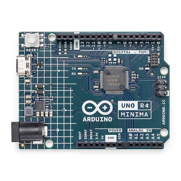
Description:
The Arduino UNO R4 Minima is a notable advancement incorporating a powerful 32-bit Renesas microcontroller, offering superior processing and memory over the Arduino UNO R3. The 32-bit architecture allows more complex and demanding projects. It features 32 kB SRAM and 256 kB flash, a 12-bit DAC, CAN BUS interface, operational amplifier, and supports power input up to 24 V. The USB-C connector aligns it with modern connectivity standards.
Principle of Work:
Internal Operation:
- Uses the 32-bit Renesas microcontroller as the brain to process instructions and tasks.
- Interfaces with onboard memory (32 kB SRAM, 256 kB flash) for storing programs and data.
- Digital and analog pins facilitate I/O with sensors, displays, and other devices.
- Onboard peripherals like the 12-bit DAC, CAN BUS, and operational amplifier enhance functionality.
Integration into Projects:
- Develop code in Arduino IDE and upload via USB-C.
- Connect sensors, actuators, and components to pins for data gathering/control.
- Expanded memory supports complex applications.
- Wide power input range (6-24 V) enables flexible power options like batteries and solar.
- USB-C connector simplifies programming and debugging.
Pinout of the Module:
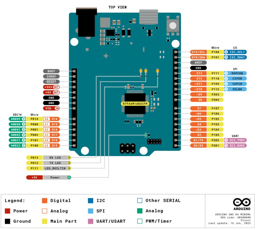
| Pin | Description | Pin | Description |
|---|---|---|---|
| D0 | Digital input/output pin 0 | D1 | Digital input/output pin 1 |
| D2 | Digital input/output pin 2 | D3 | Digital input/output pin 3 (PWM) |
| D4 | Digital input/output pin 4 (PWM) | D5 | Digital input/output pin 5 (PWM) |
| D6 | Digital input/output pin 6 (PWM) | D7 | Digital input/output pin 7 |
| D8 | Digital input/output pin 8 (PWM) | D9 | Digital input/output pin 9 (PWM) |
| D10 | Digital input/output pin 10 (PWM, SPI) | D11 | Digital input/output pin 11 (PWM, SPI) |
| D12 | Digital input/output pin 12 (PWM, SPI) | D13 | Digital input/output pin 13 (PWM, SPI) |
| A0 | Analog input pin 0 | A1 | Analog input pin 1 |
| A2 | Analog input pin 2 | A3 | Analog input pin 3 |
| A4 | Analog input pin 4 (I2C) | A5 | Analog input pin 5 (I2C) |
| GND | Ground | 5V | 5 V power output |
| 3V3 | 3.3 V power output | VIN | Input voltage (6-24 V) |
| AREF | Reference voltage for analog inputs (0-5 V) | RESET | Reset button |
| TX | Serial transmit pin | RX | Serial receive pin |
| I2C | I2C bus pins (SDA, SCL) | SPI | SPI bus pins (SCK, MOSI, MISO) |
| CAN | CAN bus pins (CAN_H, CAN_L) |
Applications:
- IoT Projects: Collect and transmit data using the board's connectivity and processing power.
- Automation and Control: Smart lighting, HVAC, and industrial automation systems.
- Data Logging and Monitoring: Store and analyze sensor data and experiments.
- Robotics: Educational or advanced robotics projects.
- Audio and Signal Processing: Using onboard DAC and operational amplifier.
- Networking and Communication: Automotive and industrial communication via CAN-BUS.
- Prototyping and Development: Ideal for experimenting and building new electronics projects.
- Education: Teaching electronics, programming, and microcontrollers.
- Home Automation: Control lights, appliances, and security features.
- Environmental Monitoring: Measure temperature, humidity, air quality, etc.
Circuit Example:
No external circuit needed to blink the onboard LED.
Library:
No library needed.
Code Example:
This code blinks the onboard LED using a bitwise XOR operation to toggle the LED state every second.
// Blink the onboard LED on the Arduino UNO R4 Minima using bitwise XOR operation
const int LED_PIN = 13;

void setup() {
  pinMode(LED_PIN, OUTPUT);
}

void loop() {
  digitalWrite(LED_PIN, digitalRead(LED_PIN) ^ 1);
  delay(1000);
}
Code Explanation:
- Define the LED Pin: Sets LED_PIN to 13, the onboard LED pin.
- Setup Function: Configures the LED pin as an output.
- Loop Function:
digitalWrite(LED_PIN, digitalRead(LED_PIN) ^ 1);toggles LED state by XORing the current state.delay(1000);pauses for 1 second.
Technical Details:
| Category | Specification |
|---|---|
| Board Name | Arduino® UNO R4 Minima |
| SKU | ABX00080 |
| Microcontroller | Renesas RA4M1 (Arm® Cortex®-M4) |
| USB | USB-C® Programming Port |
| Digital I/O Pins | 14 |
| Analog Input Pins | 6 |
| DAC | 1 (12-bit) |
| PWM Pins | 6 |
| Communication | UART (1x), I2C (1x), SPI (1x), CAN (1x) |
| Operating Voltage | 5 V |
| Input Voltage (VIN) | 6-24 V |
| DC Current per I/O Pin | 8 mA |
| Clock Speed | 48 MHz |
| Memory | 256 kB Flash, 32 kB RAM |
| Dimensions | 68.85 mm (W) x 53.34 mm (L) |
Comparisons with Arduino Uno Rev 3:
- Microcontroller: UNO R4 Minima uses 32-bit Arm Cortex-M4; Uno R3 uses 8-bit AVR.
- USB: UNO R4 Minima uses USB-C; Uno R3 uses USB-B.
- Communication: UNO R4 Minima supports CAN Bus; Uno R3 does not.
- Power Input Range: UNO R4 Minima 6-24 V; Uno R3 7-12 V.
- Clock Speed: UNO R4 Minima 48 MHz; Uno R3 16 MHz.
- Memory: UNO R4 Minima has much more flash and RAM.
- Dimensions: Similar physical size.
Features:
- Increased memory: 32 kB SRAM and 256 kB flash memory, much more than previous UNO boards for complex projects.
- Faster clock speed: 48 MHz, twice as fast as previous UNO boards for real-time processing and high-speed data transfer.
- More onboard peripherals: Includes a 12-bit DAC, CAN BUS, and operational amplifier for enhanced flexibility.
- Extended 24 V tolerance: Can be powered up to 24 V, enabling easier use with batteries or solar panels.
- USB-C® connector: Modern and versatile USB-C port, first on an UNO board.
- 12-bit DAC: For generating analog signals like audio waveforms or control voltages.
- CAN BUS: High-speed communication for industrial and automotive applications.
- Operational amplifier: For signal amplification, inversion, and filtering.
Description:
The Arduino UNO R4 Minima is a notable advancement incorporating a powerful 32-bit Renesas microcontroller, offering superior processing and memory over the Arduino UNO R3. The 32-bit architecture allows more complex and demanding projects. It features 32 kB SRAM and 256 kB flash, a 12-bit DAC, CAN BUS interface, operational amplifier, and supports power input up to 24 V. The USB-C connector aligns it with modern connectivity standards.
Principle of Work:
Internal Operation:
- Uses the 32-bit Renesas microcontroller as the brain to process instructions and tasks.
- Interfaces with onboard memory (32 kB SRAM, 256 kB flash) for storing programs and data.
- Digital and analog pins facilitate I/O with sensors, displays, and other devices.
- Onboard peripherals like the 12-bit DAC, CAN BUS, and operational amplifier enhance functionality.
Integration into Projects:
- Develop code in Arduino IDE and upload via USB-C.
- Connect sensors, actuators, and components to pins for data gathering/control.
- Expanded memory supports complex applications.
- Wide power input range (6-24 V) enables flexible power options like batteries and solar.
- USB-C connector simplifies programming and debugging.
Pinout of the Module:
| Pin | Description | Pin | Description |
|---|---|---|---|
| D0 | Digital input/output pin 0 | D1 | Digital input/output pin 1 |
| D2 | Digital input/output pin 2 | D3 | Digital input/output pin 3 (PWM) |
| D4 | Digital input/output pin 4 (PWM) | D5 | Digital input/output pin 5 (PWM) |
| D6 | Digital input/output pin 6 (PWM) | D7 | Digital input/output pin 7 |
| D8 | Digital input/output pin 8 (PWM) | D9 | Digital input/output pin 9 (PWM) |
| D10 | Digital input/output pin 10 (PWM, SPI) | D11 | Digital input/output pin 11 (PWM, SPI) |
| D12 | Digital input/output pin 12 (PWM, SPI) | D13 | Digital input/output pin 13 (PWM, SPI) |
| A0 | Analog input pin 0 | A1 | Analog input pin 1 |
| A2 | Analog input pin 2 | A3 | Analog input pin 3 |
| A4 | Analog input pin 4 (I2C) | A5 | Analog input pin 5 (I2C) |
| GND | Ground | 5V | 5 V power output |
| 3V3 | 3.3 V power output | VIN | Input voltage (6-24 V) |
| AREF | Reference voltage for analog inputs (0-5 V) | RESET | Reset button |
| TX | Serial transmit pin | RX | Serial receive pin |
| I2C | I2C bus pins (SDA, SCL) | SPI | SPI bus pins (SCK, MOSI, MISO) |
| CAN | CAN bus pins (CAN_H, CAN_L) |
Applications:
- IoT Projects: Collect and transmit data using the board's connectivity and processing power.
- Automation and Control: Smart lighting, HVAC, and industrial automation systems.
- Data Logging and Monitoring: Store and analyze sensor data and experiments.
- Robotics: Educational or advanced robotics projects.
- Audio and Signal Processing: Using onboard DAC and operational amplifier.
- Networking and Communication: Automotive and industrial communication via CAN-BUS.
- Prototyping and Development: Ideal for experimenting and building new electronics projects.
- Education: Teaching electronics, programming, and microcontrollers.
- Home Automation: Control lights, appliances, and security features.
- Environmental Monitoring: Measure temperature, humidity, air quality, etc.
Circuit Example:
No external circuit needed to blink the onboard LED.
Library:
No library needed.
Code Example:
This code blinks the onboard LED using a bitwise XOR operation to toggle the LED state every second.
// Blink the onboard LED on the Arduino UNO R4 Minima using bitwise XOR operation
const int LED_PIN = 13;

void setup() {
  pinMode(LED_PIN, OUTPUT);
}

void loop() {
  digitalWrite(LED_PIN, digitalRead(LED_PIN) ^ 1);
  delay(1000);
}
Code Explanation:
- Define the LED Pin: Sets LED_PIN to 13, the onboard LED pin.
- Setup Function: Configures the LED pin as an output.
- Loop Function:
digitalWrite(LED_PIN, digitalRead(LED_PIN) ^ 1);toggles LED state by XORing the current state.delay(1000);pauses for 1 second.
Technical Details:
| Category | Specification |
|---|---|
| Board Name | Arduino® UNO R4 Minima |
| SKU | ABX00080 |
| Microcontroller | Renesas RA4M1 (Arm® Cortex®-M4) |
| USB | USB-C® Programming Port |
| Digital I/O Pins | 14 |
| Analog Input Pins | 6 |
| DAC | 1 (12-bit) |
| PWM Pins | 6 |
| Communication | UART (1x), I2C (1x), SPI (1x), CAN (1x) |
| Operating Voltage | 5 V |
| Input Voltage (VIN) | 6-24 V |
| DC Current per I/O Pin | 8 mA |
| Clock Speed | 48 MHz |
| Memory | 256 kB Flash, 32 kB RAM |
| Dimensions | 68.85 mm (W) x 53.34 mm (L) |
Comparisons with Arduino Uno Rev 3:
- Microcontroller: UNO R4 Minima uses 32-bit Arm Cortex-M4; Uno R3 uses 8-bit AVR.
- USB: UNO R4 Minima uses USB-C; Uno R3 uses USB-B.
- Communication: UNO R4 Minima supports CAN Bus; Uno R3 does not.
- Power Input Range: UNO R4 Minima 6-24 V; Uno R3 7-12 V.
- Clock Speed: UNO R4 Minima 48 MHz; Uno R3 16 MHz.
- Memory: UNO R4 Minima has much more flash and RAM.
- Dimensions: Similar physical size.