Features
-
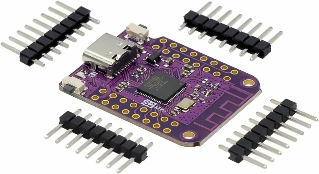
Built on the powerful ESP32-S2FN4R2 WiFi IC
-
USB Type-C interface for easy programming and power
-
27 Digital I/O pins, all supporting:
-
Interrupts
-
PWM
-
I²C
-
One-Wire communication
-
-
Onboard hardware peripherals include:
-
ADC (Analog to Digital Converter)
-
DAC (Digital to Analog Converter)
-
I²C
-
SPI
-
UART
-
USB OTG
-
-
Compatible with MicroPython and Arduino IDE
-
Preloaded with MicroPython firmware
Specifications
| Parameter | Value |
|---|---|
| Chipset | ESP32-S2FN4R2 |
| Flash | 4MB embedded flash |
| PSRAM | 2MB embedded PSRAM |
| WiFi | 2.4GHz, IEEE 802.11 b/g/n |
| USB Interface | Type-C USB |
| Digital I/O Pins | 27 pins |
| ADC Channels | Yes |
| DAC Channels | Yes |
| Communication Interfaces | UART, SPI, I2C, I2S, USB OTG |
| Programming Support | MicroPython, Arduino |
| Default Firmware | MicroPython |
| Power Supply | 3.3V or via USB |
| Board Dimensions | Mini form factor (similar to ESP8266 boards) |
Pinout
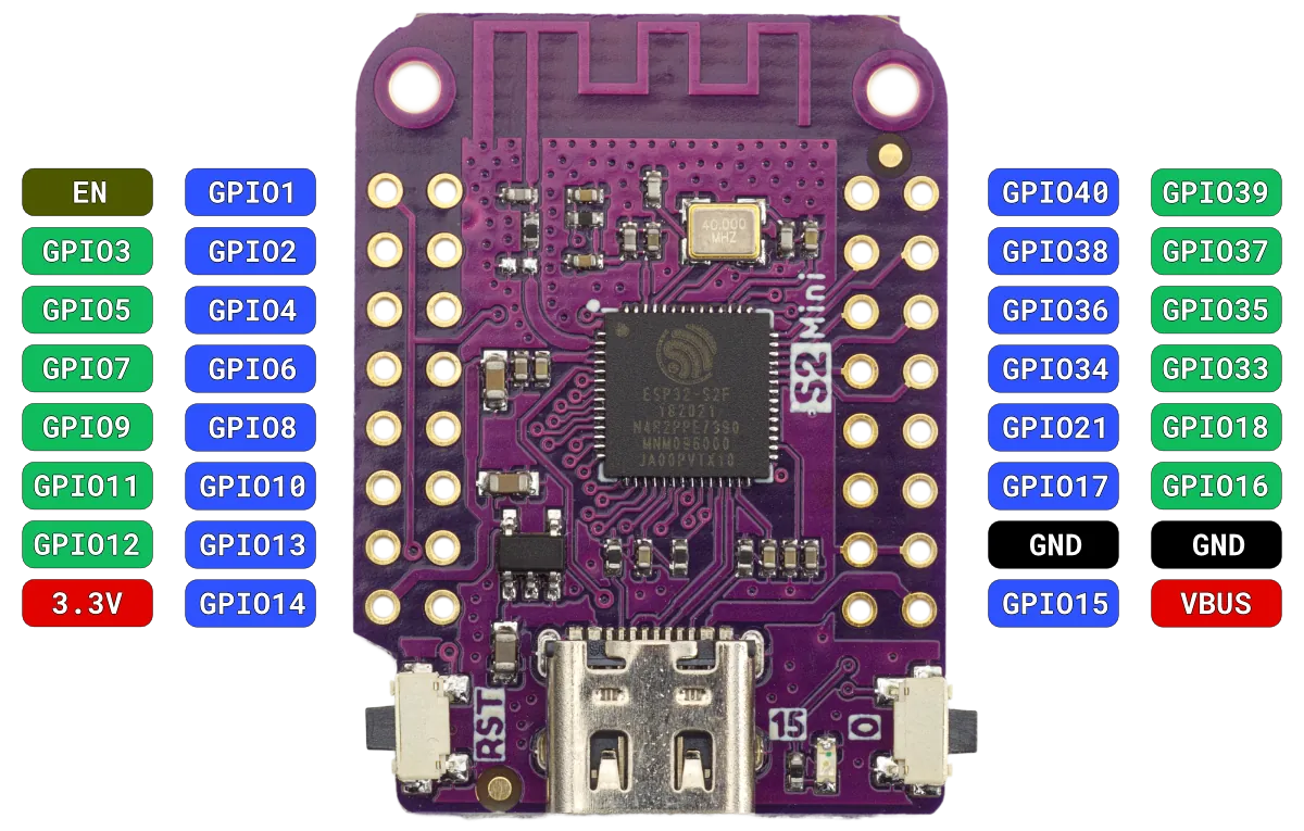
The ESP32-S2 Mini exposes a wide range of GPIOs suitable for various digital and analog functions. Here are some notable pin features:
-
GPIOs: 27 multifunctional pins
-
Power Pins: 3.3V, GND
-
Communication Pins:
-
UART TX/RX
-
SPI (MOSI, MISO, SCK, CS)
-
I²C (SDA, SCL)
-
-
Analog Pins: Multiple ADC and DAC capable pins
-
USB OTG capable via dedicated pins
Note
This board does not automatically appear on your computer when connecting to an IDE. To enter programming mode:
-
Press and hold the "0" (BOOT) button
-
While holding the "0" button, press and release the "RST" (Reset) button
-
Then release the "0" button
-
The board will now appear on a COM port for uploading firmware
Let me know if you want this in HTML or printable PDF format!
Features
-
Built on the powerful ESP32-S2FN4R2 WiFi IC
-
USB Type-C interface for easy programming and power
-
27 Digital I/O pins, all supporting:
-
Interrupts
-
PWM
-
I²C
-
One-Wire communication
-
-
Onboard hardware peripherals include:
-
ADC (Analog to Digital Converter)
-
DAC (Digital to Analog Converter)
-
I²C
-
SPI
-
UART
-
USB OTG
-
-
Compatible with MicroPython and Arduino IDE
-
Preloaded with MicroPython firmware
Specifications
| Parameter | Value |
|---|---|
| Chipset | ESP32-S2FN4R2 |
| Flash | 4MB embedded flash |
| PSRAM | 2MB embedded PSRAM |
| WiFi | 2.4GHz, IEEE 802.11 b/g/n |
| USB Interface | Type-C USB |
| Digital I/O Pins | 27 pins |
| ADC Channels | Yes |
| DAC Channels | Yes |
| Communication Interfaces | UART, SPI, I2C, I2S, USB OTG |
| Programming Support | MicroPython, Arduino |
| Default Firmware | MicroPython |
| Power Supply | 3.3V or via USB |
| Board Dimensions | Mini form factor (similar to ESP8266 boards) |
Pinout
The ESP32-S2 Mini exposes a wide range of GPIOs suitable for various digital and analog functions. Here are some notable pin features:
-
GPIOs: 27 multifunctional pins
-
Power Pins: 3.3V, GND
-
Communication Pins:
-
UART TX/RX
-
SPI (MOSI, MISO, SCK, CS)
-
I²C (SDA, SCL)
-
-
Analog Pins: Multiple ADC and DAC capable pins
-
USB OTG capable via dedicated pins
Note
This board does not automatically appear on your computer when connecting to an IDE. To enter programming mode:
-
Press and hold the "0" (BOOT) button
-
While holding the "0" button, press and release the "RST" (Reset) button
-
Then release the "0" button
-
The board will now appear on a COM port for uploading firmware
Let me know if you want this in HTML or printable PDF format!