
Each terminal is clearly labeled, eliminating the need to manually count GPIO pins during wiring. Users can simply insert wires into the terminal block and tighten them using the included screwdriver. The breakout board can also be removed easily while keeping wires connected, making it simple to switch between projects without rewiring.
Note: Ensure that the board is installed in the correct orientation when connecting it to the Raspberry Pi GPIO header. The included label sheet must be applied by the user to identify the terminals.

Features
- Terminal expansion board for Raspberry Pi 40 pin GPIO header
- Each GPIO pin broken out to an individual screw terminal
- Clear labeling for easy identification of GPIO pins
- Acrylic base with mounting hardware included
- Compact and convenient prototyping solution
- Quick connection for jumper wires and prototyping cables
- Easy to remove and reuse for different projects
- Ideal for learning, testing, and electronics development
Specifications
- Compatible GPIO Header: 2 x 20 pin Raspberry Pi GPIO
- Number of Terminals: 40
- Connection Type: Screw terminal blocks
- Base Material: Acrylic
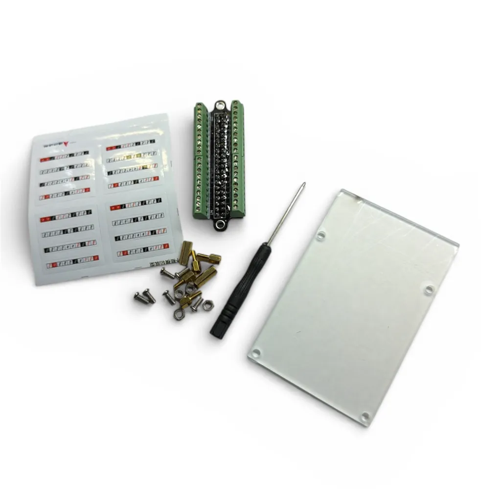
- Mounting Hardware: Copper pillars and screws
- Assembly: User assembly required
How to Use
- Attach the copper pillars and acrylic base using the provided screws to create a stable mounting platform.
- Connect the breakout board to the Raspberry Pi 40 pin GPIO header carefully, ensuring the correct orientation.
- Apply the provided terminal label stickers to identify each GPIO pin clearly.
- Insert stripped wires into the screw terminal blocks and tighten them using the included screwdriver.
- Connect sensors, LEDs, relays, or other components directly to the corresponding GPIO terminals.
- Use jumper wires from the terminals to breadboards or external circuits for prototyping.

Practical Tips
- Always power off the Raspberry Pi before connecting or removing wires from the terminals.
- Strip only a small portion of wire insulation to prevent accidental short circuits.
- Use color coded wires to make debugging and circuit tracing easier.
- Double check GPIO pin numbers before connecting power or sensitive components.
- Avoid connecting 5V devices directly to GPIO pins since Raspberry Pi GPIO operates at 3.3V logic.
- Secure wires firmly but do not overtighten the terminal screws.
- Label external connections when working on complex projects.

Common Applications
- Prototyping Raspberry Pi electronics projects
- Connecting sensors and modules
- Building home automation systems
- Testing GPIO circuits
- Educational electronics learning kits
- Robotics control systems
Each terminal is clearly labeled, eliminating the need to manually count GPIO pins during wiring. Users can simply insert wires into the terminal block and tighten them using the included screwdriver. The breakout board can also be removed easily while keeping wires connected, making it simple to switch between projects without rewiring.
Note: Ensure that the board is installed in the correct orientation when connecting it to the Raspberry Pi GPIO header. The included label sheet must be applied by the user to identify the terminals.
Features
- Terminal expansion board for Raspberry Pi 40 pin GPIO header
- Each GPIO pin broken out to an individual screw terminal
- Clear labeling for easy identification of GPIO pins
- Acrylic base with mounting hardware included
- Compact and convenient prototyping solution
- Quick connection for jumper wires and prototyping cables
- Easy to remove and reuse for different projects
- Ideal for learning, testing, and electronics development
Specifications
- Compatible GPIO Header: 2 x 20 pin Raspberry Pi GPIO
- Number of Terminals: 40
- Connection Type: Screw terminal blocks
- Base Material: Acrylic
- Mounting Hardware: Copper pillars and screws
- Assembly: User assembly required
How to Use
- Attach the copper pillars and acrylic base using the provided screws to create a stable mounting platform.
- Connect the breakout board to the Raspberry Pi 40 pin GPIO header carefully, ensuring the correct orientation.
- Apply the provided terminal label stickers to identify each GPIO pin clearly.
- Insert stripped wires into the screw terminal blocks and tighten them using the included screwdriver.
- Connect sensors, LEDs, relays, or other components directly to the corresponding GPIO terminals.
- Use jumper wires from the terminals to breadboards or external circuits for prototyping.
Practical Tips
- Always power off the Raspberry Pi before connecting or removing wires from the terminals.
- Strip only a small portion of wire insulation to prevent accidental short circuits.
- Use color coded wires to make debugging and circuit tracing easier.
- Double check GPIO pin numbers before connecting power or sensitive components.
- Avoid connecting 5V devices directly to GPIO pins since Raspberry Pi GPIO operates at 3.3V logic.
- Secure wires firmly but do not overtighten the terminal screws.
- Label external connections when working on complex projects.
Common Applications
- Prototyping Raspberry Pi electronics projects
- Connecting sensors and modules
- Building home automation systems
- Testing GPIO circuits
- Educational electronics learning kits
- Robotics control systems