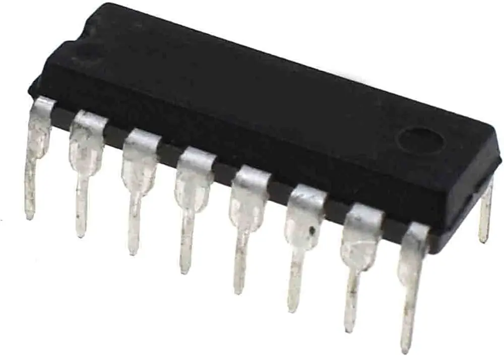
Features
- 4-bit BCD input to 7-segment display decoder and driver.
- Designed for common cathode 7-segment LED displays.
- Integrated BCD latch for storing input data.
- Directly drives LED display segments without additional decoder circuits.
- Supports Lamp Test function for checking display operation.
- Includes Blanking input for disabling display output.
- Latch Enable input allows display data storage and control.
- High output drive capability for LED display applications.
- Low power CMOS operation.
- Compatible with Arduino, microcontrollers, counters, and digital logic circuits.
Principle of Operation
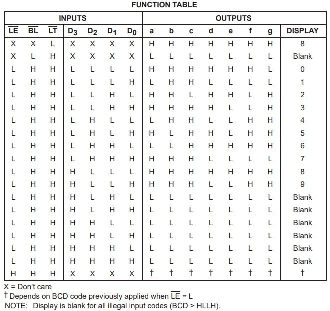
The CD4511 receives a 4-bit Binary Coded Decimal (BCD) signal through its input pins A, B, C, and D. The internal decoder converts this binary value into seven separate output signals that control the segments of a common cathode 7-segment display.
When a valid BCD value from 0000 to 1001 is applied, the IC activates the required segments to show the corresponding decimal digit from 0 to 9. The internal latch can store the input value, while the Lamp Test and Blanking pins provide additional control over display operation.
Applications
- Digital clocks and timers
- Digital counters
- Frequency meters
- Voltage and current displays
- Arduino 7-segment display projects
- Educational electronics experiments
- Industrial control panels
- Measurement instruments
- Embedded display systems
- Logic circuit demonstrations
Pinout
| Pin | Function |
|---|---|
| 1 | B Input (BCD) |
| 2 | C Input (BCD) |
| 3 | LT - Lamp Test Input |
| 4 | BI - Blanking Input |
| 5 | LE / Latch Enable |
| 6 | D Input (BCD) |
| 7 | A Input (BCD) |
| 8 | VSS - Ground |
| 9 | Segment E Output |
| 10 | Segment D Output |
| 11 | Segment C Output |
| 12 | Segment B Output |
| 13 | Segment A Output |
| 14 | Segment F Output |
| 15 | Segment G Output |
| 16 | VDD - Supply Voltage |
Wiring
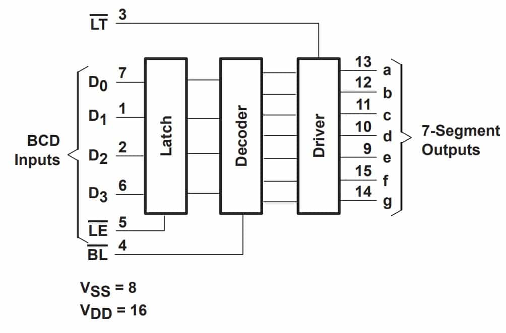
Connect the CD4511 between the digital controller and a common cathode 7-segment display. The four BCD input pins receive binary data from a microcontroller or logic circuit, while the seven output pins connect to the display segments through current-limiting resistors.
| CD4511 Pin | Connection |
|---|---|
| A, B, C, D | 4-bit BCD input source (Arduino, counter, logic circuit) |
| a-g Outputs | 7-segment display segment pins through resistors |
| VDD | Positive supply voltage |
| VSS | Ground |
| LT | Keep HIGH for normal operation |
| BI | Keep HIGH for normal display operation |
| LE | Control latch function or connect according to application |
Specifications
| Product Type | BCD to 7-Segment Display Decoder Driver IC |
| IC Model | CD4511 / CD4511B |
| Logic Family | CMOS CD4000 Series |
| Input Type | 4-Bit BCD Input |
| Display Type | Common Cathode 7-Segment LED Display |
| Supply Voltage | 5V, 10V, 15V |
| Output Capability | High-output sourcing capability up to 25mA |
| Control Inputs | Latch Enable, Lamp Test, Blanking |
| Package Type | 16-Pin DIP |
| Applications | LED display driving, counters, clocks, measurement systems |
Resources
- CD4511B Datasheet: https://www.ti.com/lit/ds/symlink/cd4511b.pdf
Features
- 4-bit BCD input to 7-segment display decoder and driver.
- Designed for common cathode 7-segment LED displays.
- Integrated BCD latch for storing input data.
- Directly drives LED display segments without additional decoder circuits.
- Supports Lamp Test function for checking display operation.
- Includes Blanking input for disabling display output.
- Latch Enable input allows display data storage and control.
- High output drive capability for LED display applications.
- Low power CMOS operation.
- Compatible with Arduino, microcontrollers, counters, and digital logic circuits.
Principle of Operation
The CD4511 receives a 4-bit Binary Coded Decimal (BCD) signal through its input pins A, B, C, and D. The internal decoder converts this binary value into seven separate output signals that control the segments of a common cathode 7-segment display.
When a valid BCD value from 0000 to 1001 is applied, the IC activates the required segments to show the corresponding decimal digit from 0 to 9. The internal latch can store the input value, while the Lamp Test and Blanking pins provide additional control over display operation.
Applications
- Digital clocks and timers
- Digital counters
- Frequency meters
- Voltage and current displays
- Arduino 7-segment display projects
- Educational electronics experiments
- Industrial control panels
- Measurement instruments
- Embedded display systems
- Logic circuit demonstrations
Pinout
| Pin | Function |
|---|---|
| 1 | B Input (BCD) |
| 2 | C Input (BCD) |
| 3 | LT - Lamp Test Input |
| 4 | BI - Blanking Input |
| 5 | LE / Latch Enable |
| 6 | D Input (BCD) |
| 7 | A Input (BCD) |
| 8 | VSS - Ground |
| 9 | Segment E Output |
| 10 | Segment D Output |
| 11 | Segment C Output |
| 12 | Segment B Output |
| 13 | Segment A Output |
| 14 | Segment F Output |
| 15 | Segment G Output |
| 16 | VDD - Supply Voltage |
Wiring
Connect the CD4511 between the digital controller and a common cathode 7-segment display. The four BCD input pins receive binary data from a microcontroller or logic circuit, while the seven output pins connect to the display segments through current-limiting resistors.
| CD4511 Pin | Connection |
|---|---|
| A, B, C, D | 4-bit BCD input source (Arduino, counter, logic circuit) |
| a-g Outputs | 7-segment display segment pins through resistors |
| VDD | Positive supply voltage |
| VSS | Ground |
| LT | Keep HIGH for normal operation |
| BI | Keep HIGH for normal display operation |
| LE | Control latch function or connect according to application |
Specifications
| Product Type | BCD to 7-Segment Display Decoder Driver IC |
| IC Model | CD4511 / CD4511B |
| Logic Family | CMOS CD4000 Series |
| Input Type | 4-Bit BCD Input |
| Display Type | Common Cathode 7-Segment LED Display |
| Supply Voltage | 5V, 10V, 15V |
| Output Capability | High-output sourcing capability up to 25mA |
| Control Inputs | Latch Enable, Lamp Test, Blanking |
| Package Type | 16-Pin DIP |
| Applications | LED display driving, counters, clocks, measurement systems |
Resources
- CD4511B Datasheet: https://www.ti.com/lit/ds/symlink/cd4511b.pdf