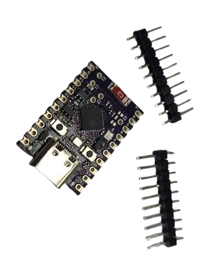
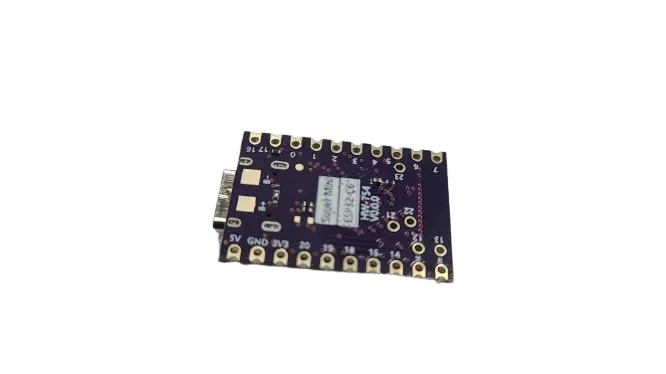
Features:
- Powerful Processor: 32-bit RISC-V CPU for efficient and high-speed processing
- Advanced Connectivity: Wi-Fi 6, Bluetooth 5.3 LE, Zigbee 3.0, and Thread 1.3 support
- Compact Size: Ultra-small 18 × 26 mm design for embedded and portable applications
- Rich GPIO: 22 programmable GPIO pins
- Multiple Interfaces: Supports SPI, I2C, UART, ADC, DAC, and PWM
- USB Type-C: Easy programming and power supply
- Onboard RGB LED: Visual indication for debugging and status
- Low Power Design: Optimized for energy-efficient IoT applications
- Development Support: Compatible with Arduino IDE, ESP-IDF, and MicroPython
- Mesh Networking: Supports Zigbee and Thread-based mesh networks
Principle of Work:
The ESP32-C6 Super Mini operates using a highly integrated SoC that combines a RISC-V CPU, wireless communication modules, and peripheral interfaces into a single chip. The processor executes user applications stored in onboard flash memory while utilizing internal SRAM for runtime data processing. The board’s standout feature is its multi-protocol wireless capability. It can communicate over Wi-Fi 6 for high-speed internet connectivity, Bluetooth 5.3 for short-range communication, and Zigbee/Thread for low-power mesh networking. This allows the board to serve as a bridge between different communication ecosystems in IoT deployments.
Its GPIO pins and communication interfaces allow seamless interaction with external sensors, displays, and actuators. The onboard USB Type-C interface enables easy programming and power delivery, while the integrated RGB LED provides immediate visual feedback for system status and debugging.
In mesh networking applications, multiple ESP32-C6 boards can form a self-healing network. One node can act as a coordinator, while others dynamically connect and relay data, ensuring stable communication even if individual nodes disconnect.
Pinout of the Module:

- Power Pins: Includes 5V input (via USB), 3.3V regulated output, and GND
- GPIO Pins: 22 programmable pins for digital input/output and peripheral control
- Analog Pins: ADC and DAC functionality for analog signal processing
- PWM Pins: Enable control of LEDs, motors, and other PWM-based devices
- I2C Interface: Dedicated pins for SDA and SCL communication
- UART Interface: TX and RX pins for serial communication
- SPI Interface: SCK, MISO, and MOSI pins for high-speed data transfer
- USB Type-C: Used for programming and power supply
- RGB LED: Onboard programmable LED for status indication
Applications:
- Smart Home Systems: Integration with Zigbee and Thread ecosystems
- IoT Devices: Wireless sensors, gateways, and cloud-connected devices
- Mesh Networks: Self-healing communication networks for large deployments
- Wearable Electronics: Compact size ideal for portable designs
- Industrial Automation: Monitoring and control systems
- Wireless Data Acquisition: Sensor networks and remote monitoring
- Robotics: Wireless control and communication
- Educational Projects: Learning platform for IoT and embedded systems
Circuit:
For a basic test, connect an external LED to a GPIO pin 2 with a current-limiting resistor. This simple circuit can be used to verify functionality by running a blink program.
Connecting with Arduino First Time
- Install Arduino IDE: Download from Arduino Official Website
- Install ESP32 Board Package: Add ESP32 board support via Boards Manager
https://espressif.github.io/arduino-esp32/package_esp32_index.json - Connect the Board: Use a USB Type-C data cable to connect the bo
- Select Board: Tools > Board > ESP32 Arduino > ESP32-C6
- Select Port: Choose the correct COM port under Tools > Port
- Upload Code: Compile and upload your sketch
Code:
// Example LED Blink Code
const int ledPin = 2; // Change according to your pinout

void setup() {
  pinMode(ledPin, OUTPUT);
}

void loop() {
  digitalWrite(ledPin, HIGH);
  delay(1000);
  digitalWrite(ledPin, LOW);
  delay(1000);
}
Technical Details:
- Processor: 32-bit RISC-V CPU
- Wireless: Wi-Fi 6, Bluetooth 5.3 LE, Zigbee 3.0, Thread 1.3
- GPIO: 22 programmable pins
- Interfaces: SPI, I2C, UART, ADC, DAC, PWM
- USB Interface: USB Type-C
- Operating Voltage: 3.3V
- Form Factor: 18 × 26 mm
- Onboard LED: RGB programmable LED
- Development Support: Arduino IDE, ESP-IDF, MicroPython
- Low Power Modes: Supported for battery-powered applications
Features:
- Powerful Processor: 32-bit RISC-V CPU for efficient and high-speed processing
- Advanced Connectivity: Wi-Fi 6, Bluetooth 5.3 LE, Zigbee 3.0, and Thread 1.3 support
- Compact Size: Ultra-small 18 × 26 mm design for embedded and portable applications
- Rich GPIO: 22 programmable GPIO pins
- Multiple Interfaces: Supports SPI, I2C, UART, ADC, DAC, and PWM
- USB Type-C: Easy programming and power supply
- Onboard RGB LED: Visual indication for debugging and status
- Low Power Design: Optimized for energy-efficient IoT applications
- Development Support: Compatible with Arduino IDE, ESP-IDF, and MicroPython
- Mesh Networking: Supports Zigbee and Thread-based mesh networks
Principle of Work:
The ESP32-C6 Super Mini operates using a highly integrated SoC that combines a RISC-V CPU, wireless communication modules, and peripheral interfaces into a single chip. The processor executes user applications stored in onboard flash memory while utilizing internal SRAM for runtime data processing. The board’s standout feature is its multi-protocol wireless capability. It can communicate over Wi-Fi 6 for high-speed internet connectivity, Bluetooth 5.3 for short-range communication, and Zigbee/Thread for low-power mesh networking. This allows the board to serve as a bridge between different communication ecosystems in IoT deployments.
Its GPIO pins and communication interfaces allow seamless interaction with external sensors, displays, and actuators. The onboard USB Type-C interface enables easy programming and power delivery, while the integrated RGB LED provides immediate visual feedback for system status and debugging.
In mesh networking applications, multiple ESP32-C6 boards can form a self-healing network. One node can act as a coordinator, while others dynamically connect and relay data, ensuring stable communication even if individual nodes disconnect.
Pinout of the Module:
- Power Pins: Includes 5V input (via USB), 3.3V regulated output, and GND
- GPIO Pins: 22 programmable pins for digital input/output and peripheral control
- Analog Pins: ADC and DAC functionality for analog signal processing
- PWM Pins: Enable control of LEDs, motors, and other PWM-based devices
- I2C Interface: Dedicated pins for SDA and SCL communication
- UART Interface: TX and RX pins for serial communication
- SPI Interface: SCK, MISO, and MOSI pins for high-speed data transfer
- USB Type-C: Used for programming and power supply
- RGB LED: Onboard programmable LED for status indication
Applications:
- Smart Home Systems: Integration with Zigbee and Thread ecosystems
- IoT Devices: Wireless sensors, gateways, and cloud-connected devices
- Mesh Networks: Self-healing communication networks for large deployments
- Wearable Electronics: Compact size ideal for portable designs
- Industrial Automation: Monitoring and control systems
- Wireless Data Acquisition: Sensor networks and remote monitoring
- Robotics: Wireless control and communication
- Educational Projects: Learning platform for IoT and embedded systems
Circuit:
For a basic test, connect an external LED to a GPIO pin 2 with a current-limiting resistor. This simple circuit can be used to verify functionality by running a blink program.
Connecting with Arduino First Time
- Install Arduino IDE: Download from Arduino Official Website
- Install ESP32 Board Package: Add ESP32 board support via Boards Manager
https://espressif.github.io/arduino-esp32/package_esp32_index.json - Connect the Board: Use a USB Type-C data cable to connect the bo
- Select Board: Tools > Board > ESP32 Arduino > ESP32-C6
- Select Port: Choose the correct COM port under Tools > Port
- Upload Code: Compile and upload your sketch
Code:
// Example LED Blink Code
const int ledPin = 2; // Change according to your pinout

void setup() {
  pinMode(ledPin, OUTPUT);
}

void loop() {
  digitalWrite(ledPin, HIGH);
  delay(1000);
  digitalWrite(ledPin, LOW);
  delay(1000);
}
Technical Details:
- Processor: 32-bit RISC-V CPU
- Wireless: Wi-Fi 6, Bluetooth 5.3 LE, Zigbee 3.0, Thread 1.3
- GPIO: 22 programmable pins
- Interfaces: SPI, I2C, UART, ADC, DAC, PWM
- USB Interface: USB Type-C
- Operating Voltage: 3.3V
- Form Factor: 18 × 26 mm
- Onboard LED: RGB programmable LED
- Development Support: Arduino IDE, ESP-IDF, MicroPython
- Low Power Modes: Supported for battery-powered applications