Specifications
| Hardware Subsystem | Detailed Engineering Parameters |
|---|---|
| Processor Architecture | Espressif ESP32-D0WD-Q6 Dual-Core Xtensa 32-bit LX6 running up to 240 MHz. |
| Memory Layout | 520 KB internal SRAM paired with 16 MB embedded SPI Flash storage. |
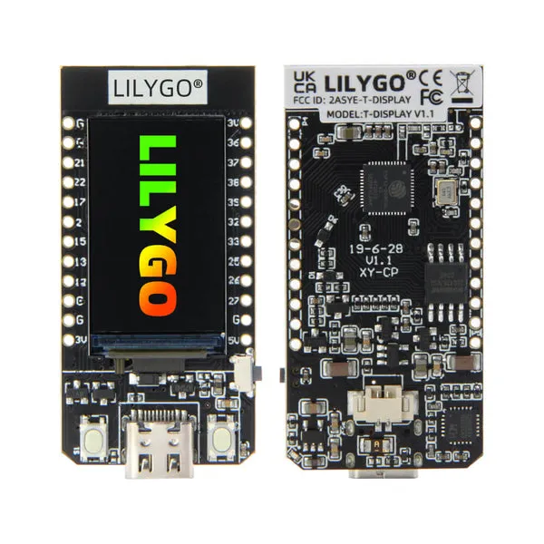
| Display Controller | 1.14" IPS TFT panel driven via 4-wire SPI by the Sitronix ST7789V chip. |
| Display Parameters | 135 × 240 active resolution, 65K RGB color space, high-density 260 PPI grid. |
| USB-to-UART Bridge | Qinheng CH9102F serial chip for automatic software flashing and monitoring. |
| Power Management | Integrated TP4054 linear charging circuit providing up to 500mA charge rate via USB. |
| Battery Interface | Dedicated 2-pin Molex PicoBlade (1.25mm pitch) connector matching 3.7V Li-Po/Li-Ion cells. |
| Physical Footprint | Compact dimensions measuring exactly 51.4mm × 25.2mm. |
Pinout
Because the internal display peripheral shares critical pins on the microchip, several GPIOs are hardwired internally. When writing software or adding sensors, take note of this system routing map:
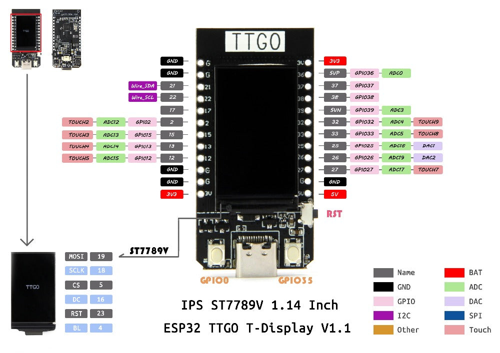
- Display SPI Lines: MOSI is routed to GPIO 19, and SCLK is routed to GPIO 18.
- Display Controls: Chip Select (CS) uses GPIO 5, DC (Data/Command) uses GPIO 16, and Reset uses GPIO 23.
- Backlight Control: The LCD background brightness is managed via GPIO 4 (supports PWM for dimming).
- Tactile User Buttons: Two on-board input buttons are wired directly to GPIO 0 and GPIO 35.
Firmware & Programming Integration
Arduino IDE Configurations
To compile code correctly without breaking the graphic runtime pipeline, utilize these target configuration selections:
- Board Manager Selection: Set target board to ESP32 Dev Module (or TTGO LoRa32-OLED V1 depending on library iteration).
- Memory Setup: Set Flash Size to 16MB (128Mb) and ensure PSRAM is set to Disabled.
- Graphics Engine Library: The official repository utilizes a custom-forked version of TFT_eSPI. For native compatibility, lock your compiler's library manager version down to 2.0.14 or lower to prevent syntax execution errors.
Developer's Safety Note: Keep the factory protective film over the IPS screen while soldering the header pins. Heat dispersion during manual soldering can cause flux splatter to cleanly pit or permanently scar the exposed acrylic polarizer layer of the screen.
Resources:
Specifications
| Hardware Subsystem | Detailed Engineering Parameters |
|---|---|
| Processor Architecture | Espressif ESP32-D0WD-Q6 Dual-Core Xtensa 32-bit LX6 running up to 240 MHz. |
| Memory Layout | 520 KB internal SRAM paired with 16 MB embedded SPI Flash storage. |
| Display Controller | 1.14" IPS TFT panel driven via 4-wire SPI by the Sitronix ST7789V chip. |
| Display Parameters | 135 × 240 active resolution, 65K RGB color space, high-density 260 PPI grid. |
| USB-to-UART Bridge | Qinheng CH9102F serial chip for automatic software flashing and monitoring. |
| Power Management | Integrated TP4054 linear charging circuit providing up to 500mA charge rate via USB. |
| Battery Interface | Dedicated 2-pin Molex PicoBlade (1.25mm pitch) connector matching 3.7V Li-Po/Li-Ion cells. |
| Physical Footprint | Compact dimensions measuring exactly 51.4mm × 25.2mm. |
Pinout
Because the internal display peripheral shares critical pins on the microchip, several GPIOs are hardwired internally. When writing software or adding sensors, take note of this system routing map:
- Display SPI Lines: MOSI is routed to GPIO 19, and SCLK is routed to GPIO 18.
- Display Controls: Chip Select (CS) uses GPIO 5, DC (Data/Command) uses GPIO 16, and Reset uses GPIO 23.
- Backlight Control: The LCD background brightness is managed via GPIO 4 (supports PWM for dimming).
- Tactile User Buttons: Two on-board input buttons are wired directly to GPIO 0 and GPIO 35.
Firmware & Programming Integration
Arduino IDE Configurations
To compile code correctly without breaking the graphic runtime pipeline, utilize these target configuration selections:
- Board Manager Selection: Set target board to ESP32 Dev Module (or TTGO LoRa32-OLED V1 depending on library iteration).
- Memory Setup: Set Flash Size to 16MB (128Mb) and ensure PSRAM is set to Disabled.
- Graphics Engine Library: The official repository utilizes a custom-forked version of TFT_eSPI. For native compatibility, lock your compiler's library manager version down to 2.0.14 or lower to prevent syntax execution errors.
Developer's Safety Note: Keep the factory protective film over the IPS screen while soldering the header pins. Heat dispersion during manual soldering can cause flux splatter to cleanly pit or permanently scar the exposed acrylic polarizer layer of the screen.