Features:
- Electrical Isolation: Provides galvanic isolation between input and output circuits.
- Infrared LED Input: Internal IR LED enables optical signal transmission.
- Phototransistor Output: Integrated NPN phototransistor for signal switching and interfacing.
- Noise Immunity: Helps eliminate ground loops and electrical interference.
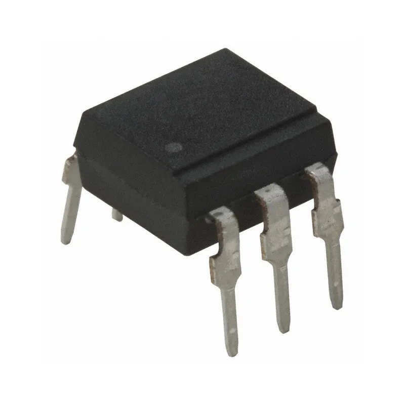
- Compact Package: Standard 6-pin DIP package suitable for breadboards and PCBs.
- Microcontroller Compatible: Ideal for Arduino, Raspberry Pi, STM32, ESP32, and other control systems.
- Reliable Performance: Designed for long-term operation in industrial and commercial applications.
- Wide Application Range: Suitable for power supplies, industrial controls, and communication interfaces.
Specifications:
- Model: 4N35
- Device Type: Optocoupler / Opto-Isolator
- Output Type: NPN Phototransistor
- Package Type: DIP-6
- Isolation Voltage: Up to 5000V RMS
- Input LED Forward Voltage: Typically 1.2V
- Collector-Emitter Voltage: Up to 70V
- Current Transfer Ratio (CTR): Typically 100% at specified test conditions
- Operating Temperature: -55°C to +100°C
- Mounting Type: Through-Hole
Pin Configuration:
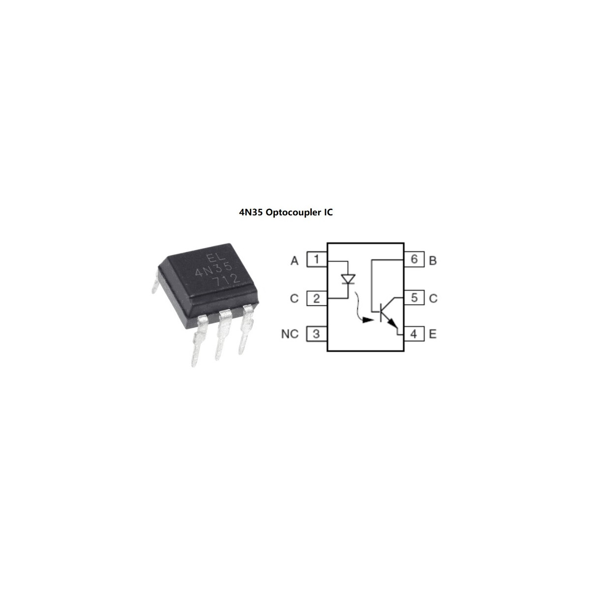
- Pin 1: Anode (LED +)
- Pin 2: Cathode (LED -)
- Pin 3: Not Connected (NC)
- Pin 4: Emitter
- Pin 5: Collector
- Pin 6: Base
How to Use:
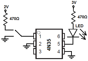
- Connect the input signal through a suitable current-limiting resistor to Pin 1 (Anode).
- Connect Pin 2 (Cathode) to the input circuit ground.
- Connect the output circuit to the Collector (Pin 5) and Emitter (Pin 4).
- Apply the input signal to activate the internal LED.
- The phototransistor output will switch accordingly while maintaining electrical isolation.
Applications:
- Microcontroller isolation
- Industrial automation systems
- PLC input and output interfaces
- Switching power supply feedback circuits
- Motor control systems
- Signal isolation circuits
- Communication interfaces
- Voltage level isolation
- Embedded electronics projects
Notes:
- Always use a current-limiting resistor with the input LED.
- Verify output current requirements when designing switching circuits.
- Isolation performance depends on proper PCB layout and spacing.
- Refer to the manufacturer's datasheet for detailed electrical characteristics.
Features:
- Electrical Isolation: Provides galvanic isolation between input and output circuits.
- Infrared LED Input: Internal IR LED enables optical signal transmission.
- Phototransistor Output: Integrated NPN phototransistor for signal switching and interfacing.
- Noise Immunity: Helps eliminate ground loops and electrical interference.
- Compact Package: Standard 6-pin DIP package suitable for breadboards and PCBs.
- Microcontroller Compatible: Ideal for Arduino, Raspberry Pi, STM32, ESP32, and other control systems.
- Reliable Performance: Designed for long-term operation in industrial and commercial applications.
- Wide Application Range: Suitable for power supplies, industrial controls, and communication interfaces.
Specifications:
- Model: 4N35
- Device Type: Optocoupler / Opto-Isolator
- Output Type: NPN Phototransistor
- Package Type: DIP-6
- Isolation Voltage: Up to 5000V RMS
- Input LED Forward Voltage: Typically 1.2V
- Collector-Emitter Voltage: Up to 70V
- Current Transfer Ratio (CTR): Typically 100% at specified test conditions
- Operating Temperature: -55°C to +100°C
- Mounting Type: Through-Hole
Pin Configuration:
- Pin 1: Anode (LED +)
- Pin 2: Cathode (LED -)
- Pin 3: Not Connected (NC)
- Pin 4: Emitter
- Pin 5: Collector
- Pin 6: Base
How to Use:
- Connect the input signal through a suitable current-limiting resistor to Pin 1 (Anode).
- Connect Pin 2 (Cathode) to the input circuit ground.
- Connect the output circuit to the Collector (Pin 5) and Emitter (Pin 4).
- Apply the input signal to activate the internal LED.
- The phototransistor output will switch accordingly while maintaining electrical isolation.
Applications:
- Microcontroller isolation
- Industrial automation systems
- PLC input and output interfaces
- Switching power supply feedback circuits
- Motor control systems
- Signal isolation circuits
- Communication interfaces
- Voltage level isolation
- Embedded electronics projects
Notes:
- Always use a current-limiting resistor with the input LED.
- Verify output current requirements when designing switching circuits.
- Isolation performance depends on proper PCB layout and spacing.
- Refer to the manufacturer's datasheet for detailed electrical characteristics.