Features:
- 10-Bit Resolution: Converts analog signals into digital values ranging from 0 to 1023.
- 8 Analog Input Channels: Supports up to eight single-ended analog inputs or four differential input pairs.
- SPI Communication Interface: Industry-standard SPI interface for fast and reliable communication.
- High Sampling Rate: Up to 200k samples per second at 5V operation.
- Wide Operating Voltage: Operates from 2.7V to 5.5V.
- Low Power Consumption: Typical active current of only 425µA.
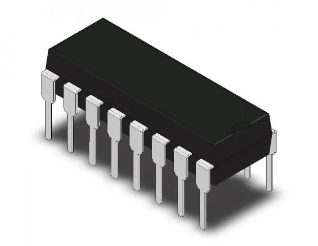
- Breadboard Friendly: Standard 16-pin DIP package for easy prototyping.
- Single-Ended and Differential Inputs: Flexible input configurations for various sensing applications.
Principle of Work:
The MCP3008 operates using Successive Approximation Register (SAR) Analog-to-Digital Conversion technology.
- Analog Signal Input: An analog voltage is applied to one of the input channels (CH0–CH7).
- Sample and Hold: The internal sample-and-hold circuit captures the input voltage.
- SAR Conversion: The SAR ADC compares the sampled voltage against internal reference levels.
- Digital Output: A 10-bit digital value (0–1023) representing the input voltage is generated.
- SPI Transmission: The conversion result is transmitted to the microcontroller through the SPI interface.
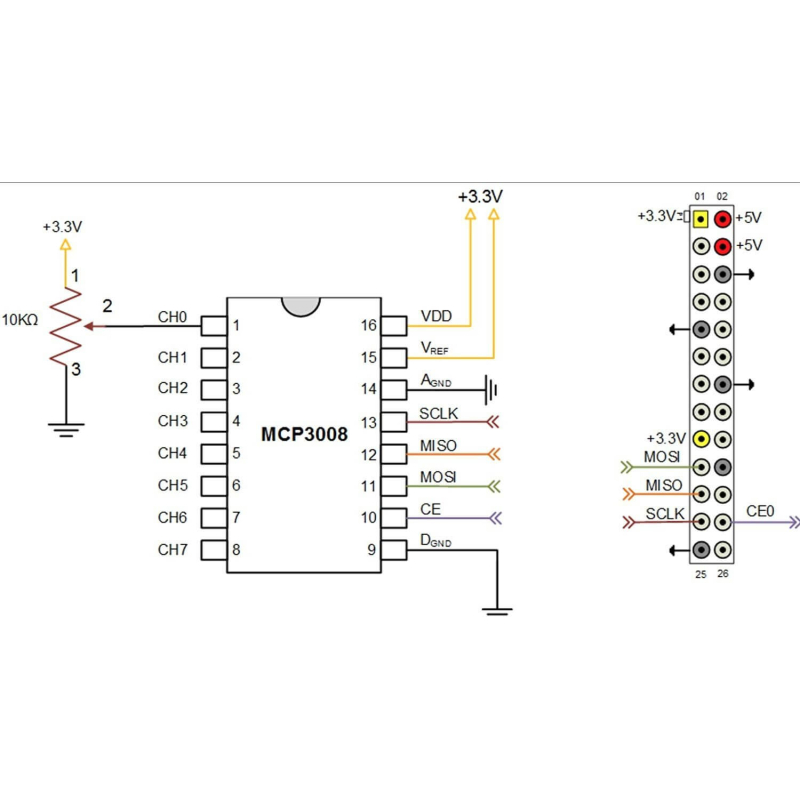
Interaction with MCU (Microcontroller Unit):
- Power Supply: Connect VDD and VREF to the desired operating voltage.
- SPI Communication: Connect CLK, DIN, DOUT, and CS to the MCU SPI pins.
- Analog Inputs: Connect sensors to CH0–CH7.
- Read ADC Values: The MCU sends commands through SPI and receives 10-bit conversion data.
- Data Processing: Convert ADC readings into voltage, temperature, pressure, light intensity, or other sensor measurements.
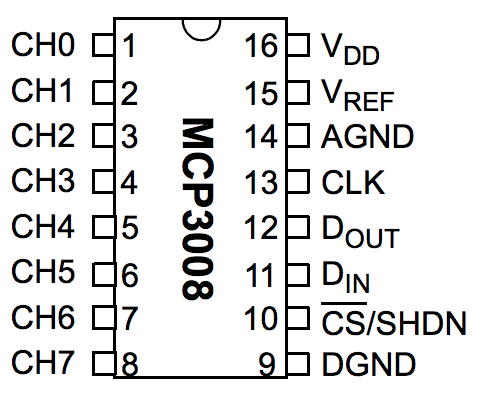
Pinout:
| Pin | Name | Description |
|---|---|---|
| 1 | CH0 | Analog Input Channel 0 |
| 2 | CH1 | Analog Input Channel 1 |
| 3 | CH2 | Analog Input Channel 2 |
| 4 | CH3 | Analog Input Channel 3 |
| 5 | CH4 | Analog Input Channel 4 |
| 6 | CH5 | Analog Input Channel 5 |
| 7 | CH6 | Analog Input Channel 6 |
| 8 | AGND | Analog Ground |
| 9 | CH7 | Analog Input Channel 7 |
| 10 | DGND | Digital Ground |
| 11 | CS/SHDN | Chip Select |
| 12 | DIN | SPI Data Input (MOSI) |
| 13 | DOUT | SPI Data Output (MISO) |
| 14 | CLK | SPI Clock |
| 15 | VREF | Reference Voltage Input |
| 16 | VDD | Power Supply |
Applications:
- Adding analog inputs to Raspberry Pi systems
- Sensor interfacing and data acquisition
- Environmental monitoring systems
- Industrial automation and control
- Robotics and autonomous systems
- Battery voltage monitoring
- Light, temperature, and pressure sensing
- Multi-channel data loggers
- Instrumentation and measurement equipment
- IoT monitoring systems
Circuit (Arduino Example):
| MCP3008 Pin | Arduino UNO |
|---|---|
| VDD | 5V |
| VREF | 5V |
| AGND | GND |
| DGND | GND |
| CLK | D13 (SCK) |
| DOUT | D12 (MISO) |
| DIN | D11 (MOSI) |
| CS | D10 (SS) |
| CH0 | Potentiometer Wiper |
Library:
For Arduino, the Adafruit MCP3008 library can be used to simplify communication with the ADC.
Code:
#include <SPI.h>
#include <Adafruit_MCP3008.h>

Adafruit_MCP3008 adc;

void setup() {
  Serial.begin(9600);
  adc.begin(10);
}

void loop() {
  int value = adc.readADC(0);

  Serial.print("CH0 = ");
  Serial.println(value);

  delay(500);
}
Code Explanation:
- Initialize SPI: Establishes SPI communication with the MCP3008.
- Configure Chip Select: Uses pin 10 as the CS pin.
- Read Channel: Retrieves the 10-bit ADC value from CH0.
- Display Result: Outputs the ADC reading to the Serial Monitor.
- Continuous Monitoring: Repeats every 500ms.
Technical Specifications:
- Model: MCP3008
- Architecture: SAR ADC
- Resolution: 10-bit
- Input Channels: 8 Single-Ended or 4 Differential
- Interface: SPI
- Sampling Rate: Up to 200ksps
- Supply Voltage: 2.7V – 5.5V
- Operating Current: Typical 425µA
- Standby Current: Typical 5nA
- Package: 16-Pin DIP
- Operating Temperature: -40°C to +85°C
- DNL: ±1 LSB
- INL: ±1 LSB
Resources:
Features:
- 10-Bit Resolution: Converts analog signals into digital values ranging from 0 to 1023.
- 8 Analog Input Channels: Supports up to eight single-ended analog inputs or four differential input pairs.
- SPI Communication Interface: Industry-standard SPI interface for fast and reliable communication.
- High Sampling Rate: Up to 200k samples per second at 5V operation.
- Wide Operating Voltage: Operates from 2.7V to 5.5V.
- Low Power Consumption: Typical active current of only 425µA.
- Breadboard Friendly: Standard 16-pin DIP package for easy prototyping.
- Single-Ended and Differential Inputs: Flexible input configurations for various sensing applications.
Principle of Work:
The MCP3008 operates using Successive Approximation Register (SAR) Analog-to-Digital Conversion technology.
- Analog Signal Input: An analog voltage is applied to one of the input channels (CH0–CH7).
- Sample and Hold: The internal sample-and-hold circuit captures the input voltage.
- SAR Conversion: The SAR ADC compares the sampled voltage against internal reference levels.
- Digital Output: A 10-bit digital value (0–1023) representing the input voltage is generated.
- SPI Transmission: The conversion result is transmitted to the microcontroller through the SPI interface.
Interaction with MCU (Microcontroller Unit):
- Power Supply: Connect VDD and VREF to the desired operating voltage.
- SPI Communication: Connect CLK, DIN, DOUT, and CS to the MCU SPI pins.
- Analog Inputs: Connect sensors to CH0–CH7.
- Read ADC Values: The MCU sends commands through SPI and receives 10-bit conversion data.
- Data Processing: Convert ADC readings into voltage, temperature, pressure, light intensity, or other sensor measurements.
Pinout:
| Pin | Name | Description |
|---|---|---|
| 1 | CH0 | Analog Input Channel 0 |
| 2 | CH1 | Analog Input Channel 1 |
| 3 | CH2 | Analog Input Channel 2 |
| 4 | CH3 | Analog Input Channel 3 |
| 5 | CH4 | Analog Input Channel 4 |
| 6 | CH5 | Analog Input Channel 5 |
| 7 | CH6 | Analog Input Channel 6 |
| 8 | AGND | Analog Ground |
| 9 | CH7 | Analog Input Channel 7 |
| 10 | DGND | Digital Ground |
| 11 | CS/SHDN | Chip Select |
| 12 | DIN | SPI Data Input (MOSI) |
| 13 | DOUT | SPI Data Output (MISO) |
| 14 | CLK | SPI Clock |
| 15 | VREF | Reference Voltage Input |
| 16 | VDD | Power Supply |
Applications:
- Adding analog inputs to Raspberry Pi systems
- Sensor interfacing and data acquisition
- Environmental monitoring systems
- Industrial automation and control
- Robotics and autonomous systems
- Battery voltage monitoring
- Light, temperature, and pressure sensing
- Multi-channel data loggers
- Instrumentation and measurement equipment
- IoT monitoring systems
Circuit (Arduino Example):
| MCP3008 Pin | Arduino UNO |
|---|---|
| VDD | 5V |
| VREF | 5V |
| AGND | GND |
| DGND | GND |
| CLK | D13 (SCK) |
| DOUT | D12 (MISO) |
| DIN | D11 (MOSI) |
| CS | D10 (SS) |
| CH0 | Potentiometer Wiper |
Library:
For Arduino, the Adafruit MCP3008 library can be used to simplify communication with the ADC.
Code:
#include <SPI.h>
#include <Adafruit_MCP3008.h>

Adafruit_MCP3008 adc;

void setup() {
  Serial.begin(9600);
  adc.begin(10);
}

void loop() {
  int value = adc.readADC(0);

  Serial.print("CH0 = ");
  Serial.println(value);

  delay(500);
}
Code Explanation:
- Initialize SPI: Establishes SPI communication with the MCP3008.
- Configure Chip Select: Uses pin 10 as the CS pin.
- Read Channel: Retrieves the 10-bit ADC value from CH0.
- Display Result: Outputs the ADC reading to the Serial Monitor.
- Continuous Monitoring: Repeats every 500ms.
Technical Specifications:
- Model: MCP3008
- Architecture: SAR ADC
- Resolution: 10-bit
- Input Channels: 8 Single-Ended or 4 Differential
- Interface: SPI
- Sampling Rate: Up to 200ksps
- Supply Voltage: 2.7V – 5.5V
- Operating Current: Typical 425µA
- Standby Current: Typical 5nA
- Package: 16-Pin DIP
- Operating Temperature: -40°C to +85°C
- DNL: ±1 LSB
- INL: ±1 LSB
Resources: