
Features:
- PC817 Optocoupler Isolation: Provides electrical isolation between input and output circuits.
- Wide Input Voltage Support: Available for 3V, 5V, 12V, and 24V control signals.
- Wide Output Voltage Range: Compatible with output voltages from 1.8V to 24V DC.
- Noise Immunity: Protects sensitive circuits from electrical interference and voltage spikes.
- Level Conversion Capability: Supports NPN-to-PNP and PNP-to-NPN signal conversion.
- Industrial-Grade Isolation: Suitable for PLCs, motor controllers, relays, and industrial automation.
- Screw Terminal Connections: 5.08mm pitch terminals provide secure and convenient wiring.
- Compact Design: Easy integration into embedded and industrial systems.
Principle of Work:

The module operates using an optocoupler, which transfers signals through light rather than direct electrical connection.
- Input Signal: A voltage applied to the input side powers an internal infrared LED inside the PC817.
- Optical Transmission: The LED emits infrared light proportional to the input signal.
- Phototransistor Detection: The internal phototransistor receives the light and switches accordingly.
- Output Signal: The output side reproduces the signal while remaining electrically isolated from the input.
- Isolation Protection: Noise, voltage spikes, and ground loops cannot directly pass between the two circuits.
Interaction with MCU (Microcontroller Unit):

- Connect MCU Output: Connect the microcontroller GPIO pin to the module input terminal.
- Signal Isolation: The PC817 optocoupler electrically isolates the MCU from the controlled device.
- Output Control: The output side can switch relays, PLC inputs, industrial controllers, or other circuits.
- Level Conversion: Signals between different voltage domains can be safely converted and transferred.
- Protection: The MCU remains protected from high-voltage transients and electrical interference.
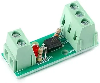
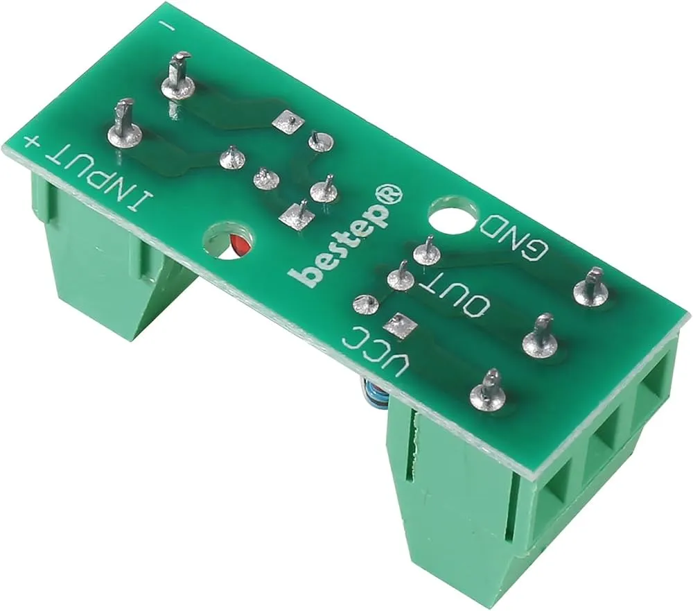
Pinout:

| Terminal | Description |
|---|---|
| IN+ | Positive Input Signal |
| IN- | Input Ground |
| OUT+ | Output Collector / Positive Output |
| OUT- | Output Emitter / Ground Output |
Applications:
- PLC input and output isolation
- Industrial automation systems
- Motor control and driver isolation
- Relay driving circuits
- Signal level conversion (NPN ↔ PNP)
- Microcontroller protection circuits
- Noise suppression in control systems
- Home automation systems
- Sensor signal isolation
- High-voltage to low-voltage interfacing
Circuit Example (Arduino to PLC Input):
| Module Pin | Arduino UNO |
|---|---|
| IN+ | D2 |
| IN- | GND |
| OUT+ | PLC Input+ |
| OUT- | PLC Input GND |
Example Wiring Diagram:
Arduino              PC817 Module              PLC

D2      -----------> IN+
GND     -----------> IN-

                     OUT+ -----------> PLC Input+
                     OUT- -----------> PLC Input GND
Library:
No library is required. The module behaves like a digital switch and can be controlled directly using standard GPIO functions.
Code:
#define OPTO_PIN 2

void setup() {
  pinMode(OPTO_PIN, OUTPUT);
}

void loop() {
  digitalWrite(OPTO_PIN, HIGH);
  delay(1000);

  digitalWrite(OPTO_PIN, LOW);
  delay(1000);
}
Code Explanation:
- Pin Definition: Assigns a GPIO pin to control the optocoupler input.
- Output Configuration: Configures the pin as an output.
- Signal ON: Sets the output HIGH, activating the optocoupler.
- Signal OFF: Sets the output LOW, deactivating the optocoupler.
- Continuous Operation: Repeats the cycle every second.
Technical Specifications:
- Optocoupler Chip: PC817
- Channels: 1
- Input Voltage Options: 3V / 5V / 12V / 24V DC
- Output Voltage Range: 1.8V – 24V DC
- Isolation Method: Optical Isolation
- Terminal Type: 5.08mm Screw Terminals
- Output Type: Open Collector Phototransistor
- Level Conversion Support: Yes
- Noise Immunity: High
- Operating Temperature: -20°C to +85°C
Resources:
Comparison:
Compared to direct transistor switching circuits, the PC817 Optocoupler Isolation Module provides complete electrical isolation between the control and load sides. This significantly improves system reliability by protecting microcontrollers, PLCs, and sensitive electronics from voltage spikes, electrical noise, and ground loop issues. It is particularly useful in industrial environments where interference and voltage differences between systems are common.
Features:
- PC817 Optocoupler Isolation: Provides electrical isolation between input and output circuits.
- Wide Input Voltage Support: Available for 3V, 5V, 12V, and 24V control signals.
- Wide Output Voltage Range: Compatible with output voltages from 1.8V to 24V DC.
- Noise Immunity: Protects sensitive circuits from electrical interference and voltage spikes.
- Level Conversion Capability: Supports NPN-to-PNP and PNP-to-NPN signal conversion.
- Industrial-Grade Isolation: Suitable for PLCs, motor controllers, relays, and industrial automation.
- Screw Terminal Connections: 5.08mm pitch terminals provide secure and convenient wiring.
- Compact Design: Easy integration into embedded and industrial systems.
Principle of Work:
The module operates using an optocoupler, which transfers signals through light rather than direct electrical connection.
- Input Signal: A voltage applied to the input side powers an internal infrared LED inside the PC817.
- Optical Transmission: The LED emits infrared light proportional to the input signal.
- Phototransistor Detection: The internal phototransistor receives the light and switches accordingly.
- Output Signal: The output side reproduces the signal while remaining electrically isolated from the input.
- Isolation Protection: Noise, voltage spikes, and ground loops cannot directly pass between the two circuits.
Interaction with MCU (Microcontroller Unit):
- Connect MCU Output: Connect the microcontroller GPIO pin to the module input terminal.
- Signal Isolation: The PC817 optocoupler electrically isolates the MCU from the controlled device.
- Output Control: The output side can switch relays, PLC inputs, industrial controllers, or other circuits.
- Level Conversion: Signals between different voltage domains can be safely converted and transferred.
- Protection: The MCU remains protected from high-voltage transients and electrical interference.
Pinout:
| Terminal | Description |
|---|---|
| IN+ | Positive Input Signal |
| IN- | Input Ground |
| OUT+ | Output Collector / Positive Output |
| OUT- | Output Emitter / Ground Output |
Applications:
- PLC input and output isolation
- Industrial automation systems
- Motor control and driver isolation
- Relay driving circuits
- Signal level conversion (NPN ↔ PNP)
- Microcontroller protection circuits
- Noise suppression in control systems
- Home automation systems
- Sensor signal isolation
- High-voltage to low-voltage interfacing
Circuit Example (Arduino to PLC Input):
| Module Pin | Arduino UNO |
|---|---|
| IN+ | D2 |
| IN- | GND |
| OUT+ | PLC Input+ |
| OUT- | PLC Input GND |
Example Wiring Diagram:
Arduino              PC817 Module              PLC

D2      -----------> IN+
GND     -----------> IN-

                     OUT+ -----------> PLC Input+
                     OUT- -----------> PLC Input GND
Library:
No library is required. The module behaves like a digital switch and can be controlled directly using standard GPIO functions.
Code:
#define OPTO_PIN 2

void setup() {
  pinMode(OPTO_PIN, OUTPUT);
}

void loop() {
  digitalWrite(OPTO_PIN, HIGH);
  delay(1000);

  digitalWrite(OPTO_PIN, LOW);
  delay(1000);
}
Code Explanation:
- Pin Definition: Assigns a GPIO pin to control the optocoupler input.
- Output Configuration: Configures the pin as an output.
- Signal ON: Sets the output HIGH, activating the optocoupler.
- Signal OFF: Sets the output LOW, deactivating the optocoupler.
- Continuous Operation: Repeats the cycle every second.
Technical Specifications:
- Optocoupler Chip: PC817
- Channels: 1
- Input Voltage Options: 3V / 5V / 12V / 24V DC
- Output Voltage Range: 1.8V – 24V DC
- Isolation Method: Optical Isolation
- Terminal Type: 5.08mm Screw Terminals
- Output Type: Open Collector Phototransistor
- Level Conversion Support: Yes
- Noise Immunity: High
- Operating Temperature: -20°C to +85°C
Resources:
Comparison:
Compared to direct transistor switching circuits, the PC817 Optocoupler Isolation Module provides complete electrical isolation between the control and load sides. This significantly improves system reliability by protecting microcontrollers, PLCs, and sensitive electronics from voltage spikes, electrical noise, and ground loop issues. It is particularly useful in industrial environments where interference and voltage differences between systems are common.