Features
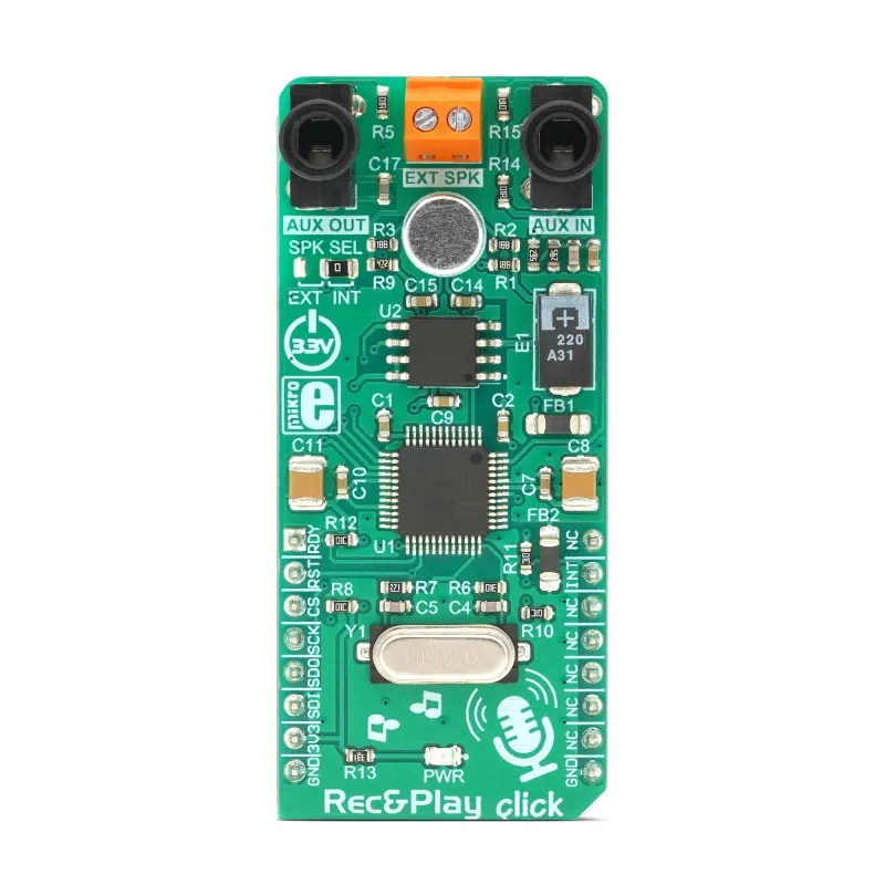
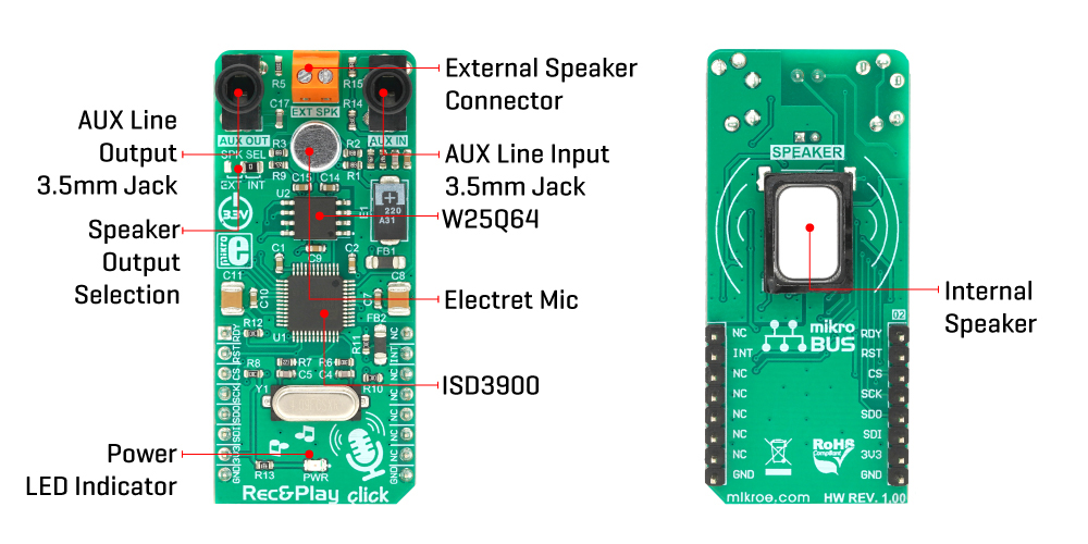
- Based on the Nuvoton ISD3900 digital voice recording and playback IC.
- Built-in ChipCorder® technology with digital audio compression.
- Stores up to approximately 32 minutes of audio.
- Integrated omnidirectional electret microphone.
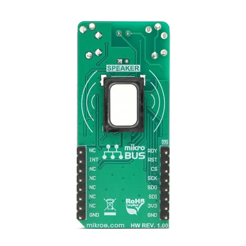
- Integrated 8Ω miniature 0.7W neodymium speaker.
- Supports external passive speaker connection.
- 3.5mm AUX input for external audio recording.
- 3.5mm AUX output for amplified speakers or headphones.
- Programmable audio signal path with multiple recording modes.
- SPI communication interface.
- Onboard 64Mbit Winbond W25Q64 serial Flash memory.
- Supports message indexing instead of fixed memory addresses.
- Voice Macro support for automated playback sequences.
- Compatible with mikroBUS™ development boards.
- mikroSDK software library available.
Principle of Operation
The Rec&Play Click is built around the ISD3900 ChipCorder®, a dedicated digital audio processor that performs recording, compression, storage management, and playback without requiring significant processing resources from the host MCU.
Audio can be captured from the onboard microphone or through the AUX input connector. The ISD3900 digitizes and compresses the audio before storing it in the onboard 64Mbit SPI Flash memory. During playback, the stored audio is decompressed internally and sent either to the onboard speaker, an external speaker, or the line output.

Communication with the host controller is performed through the SPI interface, allowing the application to record, erase, search, and play indexed audio messages while the onboard processor handles all audio processing tasks.
Applications
- Voice recording systems
- Voice prompts and announcements
- Talking consumer products
- POS terminals
- Home appliances
- Industrial control systems
- Interactive toys
- Smart kiosks
- Embedded audio projects
- Educational electronics
Pinout
| mikroBUS Pin | Function |
|---|---|
| AN | RDY (SPI Ready Status) |
| RST | Hardware Reset |
| CS | SPI Chip Select |
| SCK | SPI Clock |
| MISO | SPI Data Output |
| MOSI | SPI Data Input |
| INT | Interrupt Output |
| 3.3V | Power Supply |
| GND | Ground |
Wiring
The Rec&Play Click is designed to plug directly into any mikroBUS™ socket, where all required power and SPI signals are connected automatically.
For custom hardware or prototype boards, the required connections are:
| Rec&Play Click | Connection |
|---|---|
| 3.3V | 3.3V Supply |
| GND | Ground |
| CS | SPI Chip Select |
| SCK | SPI Clock |
| MISO | SPI MISO |
| MOSI | SPI MOSI |
| RST | GPIO (Optional) |
| INT | GPIO Interrupt (Optional) |
| AN (RDY) | GPIO Input (Optional) |
Note: The board operates exclusively at 3.3V logic levels. When interfacing with 5V microcontrollers such as the Arduino Uno, appropriate bidirectional logic-level shifting is recommended for reliable operation.
Specifications
| Product Type | Audio Recording & Playback Click Board |
| Main IC | Nuvoton ISD3900 |
| Audio Technology | ChipCorder® Digital Audio |
| Flash Memory | 64Mbit Winbond W25Q64 |
| Maximum Recording Time | Up to 32 minutes |
| Communication Interface | SPI |
| Operating Voltage | 3.3V |
| Microphone | Onboard Electret Microphone |
| Speaker | 8Ω 0.7W Miniature Speaker |
| External Speaker | Supported |
| Audio Input | 3.5mm AUX Input |
| Audio Output | 3.5mm AUX Output |
| Audio Sample Rate | Up to 32kHz |
| Crystal Frequency | 4.096MHz |
| Board Size | 57.15 × 25.4 mm (Click Board L) |
| Compatibility | mikroBUS™ |
Library Needed
- mikroSDK Rec&Play Click LibStock
- SPI Library (included with supported MCU platforms)
Simple Code
// mikroSDK example (pseudo code)
recplay_init();
recplay_recordMsg(); // Start recording
Delay_ms(5000);
recplay_stop(); // Stop recording
Delay_ms(1000);
recplay_playMsg(0,0); // Play first recorded message
The REC&PLAY Click application is divided into three main sections: System Initialization, Application Initialization, and Application Task. Each section prepares and controls the ISD3900 voice recording chip to perform recording, playback, and memory operations.
1. System Initialization
This section prepares the microcontroller hardware and communication interface required to operate the REC&PLAY Click.
- Initializes required GPIO pins.
- Configures the SPI interface used to communicate with the ISD3900.
- Configures control signals such as Chip Select, Reset, and Interrupt pins.
- Prepares the system for communication with the voice recording module.
2. Application Initialization
This section configures the ISD3900 chip and places it into a proper operating state.
- Resets the ISD3900 chip.
- Powers up the internal circuits.
- Erases previous audio data from memory.
- Configures the required clock settings.
- Initializes SPI communication parameters.
After this stage, the REC&PLAY Click is ready for recording and playback operations.
3. Application Task
The main application performs the complete recording and playback sequence. The process is repeated every 10 seconds.
- Recording Configuration:
The ISD3900 is configured for microphone recording mode before each recording operation. - Audio Recording:
The chip records an 8-second audio message and stores it in the Flash memory at a specified address. - Message Information:
The recorded message address and length are read from memory. - Playback Configuration:
The ISD3900 is reconfigured for playback mode with the required audio output settings. - Audio Playback:
The recorded message is played through the audio output. - Message Erasing:
After playback is completed, the recorded message is erased from memory to prepare for a new recording.
Operation Flow
Initialize System
        ↓
Initialize ISD3900
        ↓
Configure Recording Mode
        ↓
Record Audio Message (8 seconds)
        ↓
Read Message Information
        ↓
Configure Playback Mode
        ↓
Play Recorded Message
        ↓
Erase Message
        ↓
Repeat After 10 Seconds
Important Note
The ISD3900 requires a specific configuration for each operation mode. The chip must be configured for recording mode whenever a new message is recorded, and it must be configured again for playback mode whenever a stored message is played.
void applicationTask()
{
    mikrobus_logWrite( "Preparing to record a message...", _LOG_LINE );
    for (i = 0; i < 32; i++)
    {
        if ((i != _RECPLAY_CFG0A_REG) && (i != _RECPLAY_CFG1C_REG) && (i != _RECPLAY_CFG1E_REG))
        {
            waitReady();
            tempVar = configRecMic[ i ];
            statusByte = recplay_writeCnfgReg( i, &tempVar, 1 );
        }
    }
    waitReady();
    Delay_ms( 2000 );

    mikrobus_logWrite( "Message Recording", _LOG_TEXT );
    statusByte = recplay_recordMsgAddr( 0x12000 );
    timeRecord( 8 );
    statusByte = recplay_stop();
    waitCmdFin();
    mikrobus_logWrite( "End of recording", _LOG_LINE );

    mikrobus_logWrite( "---------------------------------------", _LOG_LINE );
    statusByte = recplay_readMsgAddr( &messageAddr, &messageLength );
    LongWordToHex( messageAddr, text );
    mikrobus_logWrite( "Message Address: 0x", _LOG_TEXT );
    mikrobus_logWrite( text, _LOG_LINE );
    WordToStr( messageLength, text );
    mikrobus_logWrite( "Message Length: ", _LOG_TEXT );
    mikrobus_logWrite( text, _LOG_LINE );
    mikrobus_logWrite( "---------------------------------------", _LOG_LINE );
    Delay_ms( 1000 );

    mikrobus_logWrite( "Preparing to play a message...", _LOG_LINE );
    setVolume( 100 );
    for (i = 0; i < 32; i++)
    {
        if ((i != _RECPLAY_CFG0A_REG) && (i != _RECPLAY_CFG1C_REG) && (i != _RECPLAY_CFG1E_REG))
        {
            waitReady();
            if (i == _RECPLAY_CFG03_REG)
            {
                tempVar = volume;
            }
            else
            {
                tempVar = configPlayPwmSpk[ i ];
            }
            statusByte = recplay_writeCnfgReg( i, &tempVar, 1 );
        }
    }
    waitReady();
    Delay_ms( 2000 );

    mikrobus_logWrite( "Message is playing...", _LOG_LINE );
    statusByte = recplay_playMsg( 0x12000, 0 );
    waitCmdFin();
    mikrobus_logWrite( "End of playing", _LOG_LINE );

    mikrobus_logWrite( "---------------------------------------", _LOG_LINE );
    ByteToHex( statusByte, text );
    mikrobus_logWrite( "Status Byte: 0x", _LOG_TEXT );
    mikrobus_logWrite( text, _LOG_LINE );
    ByteToHex( interrByte, text );
    mikrobus_logWrite( "Interrupt Byte: 0x", _LOG_TEXT );
    mikrobus_logWrite( text, _LOG_LINE );
    mikrobus_logWrite( "---------------------------------------", _LOG_LINE );
    Delay_ms( 1000 );

    mikrobus_logWrite( "Message Erasing...", _LOG_LINE );
    statusByte = recplay_eraseMsg( 0x12000 );
    waitCmdFin();
    mikrobus_logWrite( "End of erasing", _LOG_LINE );

    mikrobus_logWrite( "***************************************", _LOG_LINE );
    mikrobus_logWrite( "", _LOG_LINE );
    Delay_ms( 10000 );
}
Resources
Downloads
Features
- Based on the Nuvoton ISD3900 digital voice recording and playback IC.
- Built-in ChipCorder® technology with digital audio compression.
- Stores up to approximately 32 minutes of audio.
- Integrated omnidirectional electret microphone.
- Integrated 8Ω miniature 0.7W neodymium speaker.
- Supports external passive speaker connection.
- 3.5mm AUX input for external audio recording.
- 3.5mm AUX output for amplified speakers or headphones.
- Programmable audio signal path with multiple recording modes.
- SPI communication interface.
- Onboard 64Mbit Winbond W25Q64 serial Flash memory.
- Supports message indexing instead of fixed memory addresses.
- Voice Macro support for automated playback sequences.
- Compatible with mikroBUS™ development boards.
- mikroSDK software library available.
Principle of Operation
The Rec&Play Click is built around the ISD3900 ChipCorder®, a dedicated digital audio processor that performs recording, compression, storage management, and playback without requiring significant processing resources from the host MCU.
Audio can be captured from the onboard microphone or through the AUX input connector. The ISD3900 digitizes and compresses the audio before storing it in the onboard 64Mbit SPI Flash memory. During playback, the stored audio is decompressed internally and sent either to the onboard speaker, an external speaker, or the line output.
Communication with the host controller is performed through the SPI interface, allowing the application to record, erase, search, and play indexed audio messages while the onboard processor handles all audio processing tasks.
Applications
- Voice recording systems
- Voice prompts and announcements
- Talking consumer products
- POS terminals
- Home appliances
- Industrial control systems
- Interactive toys
- Smart kiosks
- Embedded audio projects
- Educational electronics
Pinout
| mikroBUS Pin | Function |
|---|---|
| AN | RDY (SPI Ready Status) |
| RST | Hardware Reset |
| CS | SPI Chip Select |
| SCK | SPI Clock |
| MISO | SPI Data Output |
| MOSI | SPI Data Input |
| INT | Interrupt Output |
| 3.3V | Power Supply |
| GND | Ground |
Wiring
The Rec&Play Click is designed to plug directly into any mikroBUS™ socket, where all required power and SPI signals are connected automatically.
For custom hardware or prototype boards, the required connections are:
| Rec&Play Click | Connection |
|---|---|
| 3.3V | 3.3V Supply |
| GND | Ground |
| CS | SPI Chip Select |
| SCK | SPI Clock |
| MISO | SPI MISO |
| MOSI | SPI MOSI |
| RST | GPIO (Optional) |
| INT | GPIO Interrupt (Optional) |
| AN (RDY) | GPIO Input (Optional) |
Note: The board operates exclusively at 3.3V logic levels. When interfacing with 5V microcontrollers such as the Arduino Uno, appropriate bidirectional logic-level shifting is recommended for reliable operation.
Specifications
| Product Type | Audio Recording & Playback Click Board |
| Main IC | Nuvoton ISD3900 |
| Audio Technology | ChipCorder® Digital Audio |
| Flash Memory | 64Mbit Winbond W25Q64 |
| Maximum Recording Time | Up to 32 minutes |
| Communication Interface | SPI |
| Operating Voltage | 3.3V |
| Microphone | Onboard Electret Microphone |
| Speaker | 8Ω 0.7W Miniature Speaker |
| External Speaker | Supported |
| Audio Input | 3.5mm AUX Input |
| Audio Output | 3.5mm AUX Output |
| Audio Sample Rate | Up to 32kHz |
| Crystal Frequency | 4.096MHz |
| Board Size | 57.15 × 25.4 mm (Click Board L) |
| Compatibility | mikroBUS™ |
Library Needed
- mikroSDK Rec&Play Click LibStock
- SPI Library (included with supported MCU platforms)
Simple Code
// mikroSDK example (pseudo code)
recplay_init();
recplay_recordMsg(); // Start recording
Delay_ms(5000);
recplay_stop(); // Stop recording
Delay_ms(1000);
recplay_playMsg(0,0); // Play first recorded message
The REC&PLAY Click application is divided into three main sections: System Initialization, Application Initialization, and Application Task. Each section prepares and controls the ISD3900 voice recording chip to perform recording, playback, and memory operations.
1. System Initialization
This section prepares the microcontroller hardware and communication interface required to operate the REC&PLAY Click.
- Initializes required GPIO pins.
- Configures the SPI interface used to communicate with the ISD3900.
- Configures control signals such as Chip Select, Reset, and Interrupt pins.
- Prepares the system for communication with the voice recording module.
2. Application Initialization
This section configures the ISD3900 chip and places it into a proper operating state.
- Resets the ISD3900 chip.
- Powers up the internal circuits.
- Erases previous audio data from memory.
- Configures the required clock settings.
- Initializes SPI communication parameters.
After this stage, the REC&PLAY Click is ready for recording and playback operations.
3. Application Task
The main application performs the complete recording and playback sequence. The process is repeated every 10 seconds.
- Recording Configuration:
The ISD3900 is configured for microphone recording mode before each recording operation. - Audio Recording:
The chip records an 8-second audio message and stores it in the Flash memory at a specified address. - Message Information:
The recorded message address and length are read from memory. - Playback Configuration:
The ISD3900 is reconfigured for playback mode with the required audio output settings. - Audio Playback:
The recorded message is played through the audio output. - Message Erasing:
After playback is completed, the recorded message is erased from memory to prepare for a new recording.
Operation Flow
Initialize System
        ↓
Initialize ISD3900
        ↓
Configure Recording Mode
        ↓
Record Audio Message (8 seconds)
        ↓
Read Message Information
        ↓
Configure Playback Mode
        ↓
Play Recorded Message
        ↓
Erase Message
        ↓
Repeat After 10 Seconds
Important Note
The ISD3900 requires a specific configuration for each operation mode. The chip must be configured for recording mode whenever a new message is recorded, and it must be configured again for playback mode whenever a stored message is played.
void applicationTask()
{
    mikrobus_logWrite( "Preparing to record a message...", _LOG_LINE );
    for (i = 0; i < 32; i++)
    {
        if ((i != _RECPLAY_CFG0A_REG) && (i != _RECPLAY_CFG1C_REG) && (i != _RECPLAY_CFG1E_REG))
        {
            waitReady();
            tempVar = configRecMic[ i ];
            statusByte = recplay_writeCnfgReg( i, &tempVar, 1 );
        }
    }
    waitReady();
    Delay_ms( 2000 );

    mikrobus_logWrite( "Message Recording", _LOG_TEXT );
    statusByte = recplay_recordMsgAddr( 0x12000 );
    timeRecord( 8 );
    statusByte = recplay_stop();
    waitCmdFin();
    mikrobus_logWrite( "End of recording", _LOG_LINE );

    mikrobus_logWrite( "---------------------------------------", _LOG_LINE );
    statusByte = recplay_readMsgAddr( &messageAddr, &messageLength );
    LongWordToHex( messageAddr, text );
    mikrobus_logWrite( "Message Address: 0x", _LOG_TEXT );
    mikrobus_logWrite( text, _LOG_LINE );
    WordToStr( messageLength, text );
    mikrobus_logWrite( "Message Length: ", _LOG_TEXT );
    mikrobus_logWrite( text, _LOG_LINE );
    mikrobus_logWrite( "---------------------------------------", _LOG_LINE );
    Delay_ms( 1000 );

    mikrobus_logWrite( "Preparing to play a message...", _LOG_LINE );
    setVolume( 100 );
    for (i = 0; i < 32; i++)
    {
        if ((i != _RECPLAY_CFG0A_REG) && (i != _RECPLAY_CFG1C_REG) && (i != _RECPLAY_CFG1E_REG))
        {
            waitReady();
            if (i == _RECPLAY_CFG03_REG)
            {
                tempVar = volume;
            }
            else
            {
                tempVar = configPlayPwmSpk[ i ];
            }
            statusByte = recplay_writeCnfgReg( i, &tempVar, 1 );
        }
    }
    waitReady();
    Delay_ms( 2000 );

    mikrobus_logWrite( "Message is playing...", _LOG_LINE );
    statusByte = recplay_playMsg( 0x12000, 0 );
    waitCmdFin();
    mikrobus_logWrite( "End of playing", _LOG_LINE );

    mikrobus_logWrite( "---------------------------------------", _LOG_LINE );
    ByteToHex( statusByte, text );
    mikrobus_logWrite( "Status Byte: 0x", _LOG_TEXT );
    mikrobus_logWrite( text, _LOG_LINE );
    ByteToHex( interrByte, text );
    mikrobus_logWrite( "Interrupt Byte: 0x", _LOG_TEXT );
    mikrobus_logWrite( text, _LOG_LINE );
    mikrobus_logWrite( "---------------------------------------", _LOG_LINE );
    Delay_ms( 1000 );

    mikrobus_logWrite( "Message Erasing...", _LOG_LINE );
    statusByte = recplay_eraseMsg( 0x12000 );
    waitCmdFin();
    mikrobus_logWrite( "End of erasing", _LOG_LINE );

    mikrobus_logWrite( "***************************************", _LOG_LINE );
    mikrobus_logWrite( "", _LOG_LINE );
    Delay_ms( 10000 );
}