Specifications
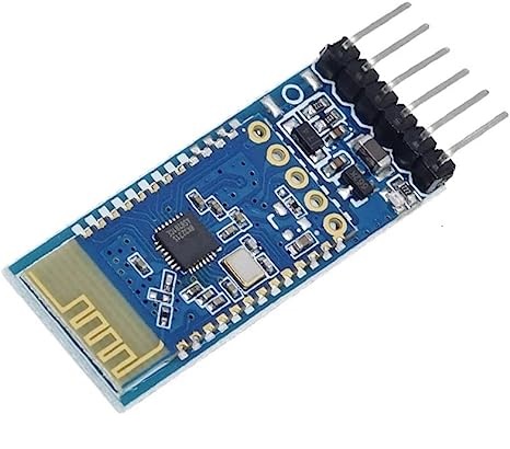
- Model: JDY-31
- Bluetooth Version: 3.0 + EDR (SPP Profile)
- Frequency: 2.4 GHz
- Communication Interface: UART
- Input Voltage: 3.6–6V (recommended 5V)
- Operating Temperature: -40°C to +80°C
- Antenna: Built-in PCB
- Transmission Distance: Up to 30 meters
- Master-Slave Support: Slave only
- Module Size: 38 × 16 mm
- STM Soldering Temperature: <260°C
- Idle Current: 4.7 mA, Connected Current: 7.3 mA
- Transmit Power: 8 dBm (max)
- Receive Sensitivity: -97 dBm
- SPP Max Throughput: 16 KB/s (Android/Windows)
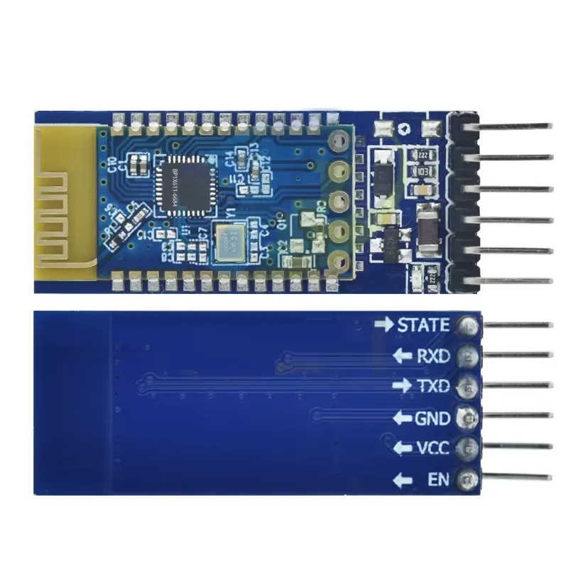
JDY-31 Pinout

| Pin | Function |
|---|---|
| VCC | Power supply (recommended 5V) |
| GND | Ground |
| TXD | Serial transmit data to external device (connect to RX of MCU) |
| RXD | Serial receive data from external device (connect to TX of MCU) |
| EN | Enable module (High = active, Low/No input = standby) |
| STATE | Indicates connection status |
How to Use
- Connect JDY-31 to a microcontroller or USB-TTL adapter using UART (cross RXD → TXD, TXD → RXD).
- Power the module with 5V and GND.
- Use a serial terminal or serial port assistant to send AT commands for configuration.
- Common AT commands:
- Query version:
AT+VERSION - Reset:
AT+RESET - Change name:
AT+NAMErainbow - Change baud:
AT+BAUD8(115200) - Set PIN:
AT+PIN1234
- Query version:
- After configuration, restart the module for changes to take effect.
Arduino Wiring Diagram
Connect the JDY-31 to Arduino as follows:
| JDY-31 Pin | Arduino Pin |
|---|---|
| VCC | 5V |
| GND | GND |
| TXD | D0 (RX) |
| RXD | D1 (TX) |
Wiring Images

Arduino Example Code
// JDY-31 Bluetooth LED Control Example
const int ledPin = 13; // LED pin on Arduino

void setup() {
  Serial.begin(9600);  // Same baud rate as JDY-31
  pinMode(ledPin, OUTPUT);
  digitalWrite(ledPin, LOW);
  Serial.println("JDY-31 Bluetooth module ready...");
}

void loop() {
  if (Serial.available() > 0) {
    char receivedChar = Serial.read();
    Serial.print("Received: ");
    Serial.println(receivedChar);

    if (receivedChar == '1') {
      digitalWrite(ledPin, HIGH);
      Serial.println("LED ON");
    } else if (receivedChar == '0') {
      digitalWrite(ledPin, LOW);
      Serial.println("LED OFF");
    }
  }
}
Applications
- Wireless serial communication with smartphones, PCs, and microcontrollers
- Smart home automation
- IoT devices and sensors
- Battery-powered wearable devices
- Remote-controlled electronics
Troubleshooting & FAQ
- No response to AT commands: Check wiring (cross RXD/TXD), baud rate (default 9600), and ensure line endings are correctly configured (\r\n).
- Phone disconnects: Check power supply stability.
- Two JDY-31 modules communicating: Not possible; JDY-31 is slave-only. Use a master-capable module (like HC-05) to connect.
- Choosing a module: Consider chip, power consumption, transmission rate, distance, interface, and master-slave mode based on project needs.
Specifications
- Model: JDY-31
- Bluetooth Version: 3.0 + EDR (SPP Profile)
- Frequency: 2.4 GHz
- Communication Interface: UART
- Input Voltage: 3.6–6V (recommended 5V)
- Operating Temperature: -40°C to +80°C
- Antenna: Built-in PCB
- Transmission Distance: Up to 30 meters
- Master-Slave Support: Slave only
- Module Size: 38 × 16 mm
- STM Soldering Temperature: <260°C
- Idle Current: 4.7 mA, Connected Current: 7.3 mA
- Transmit Power: 8 dBm (max)
- Receive Sensitivity: -97 dBm
- SPP Max Throughput: 16 KB/s (Android/Windows)
JDY-31 Pinout
| Pin | Function |
|---|---|
| VCC | Power supply (recommended 5V) |
| GND | Ground |
| TXD | Serial transmit data to external device (connect to RX of MCU) |
| RXD | Serial receive data from external device (connect to TX of MCU) |
| EN | Enable module (High = active, Low/No input = standby) |
| STATE | Indicates connection status |
How to Use
- Connect JDY-31 to a microcontroller or USB-TTL adapter using UART (cross RXD → TXD, TXD → RXD).
- Power the module with 5V and GND.
- Use a serial terminal or serial port assistant to send AT commands for configuration.
- Common AT commands:
- Query version:
AT+VERSION - Reset:
AT+RESET - Change name:
AT+NAMErainbow - Change baud:
AT+BAUD8(115200) - Set PIN:
AT+PIN1234
- Query version:
- After configuration, restart the module for changes to take effect.
Arduino Wiring Diagram
Connect the JDY-31 to Arduino as follows:
| JDY-31 Pin | Arduino Pin |
|---|---|
| VCC | 5V |
| GND | GND |
| TXD | D0 (RX) |
| RXD | D1 (TX) |
Wiring Images
Arduino Example Code
// JDY-31 Bluetooth LED Control Example
const int ledPin = 13; // LED pin on Arduino

void setup() {
  Serial.begin(9600);  // Same baud rate as JDY-31
  pinMode(ledPin, OUTPUT);
  digitalWrite(ledPin, LOW);
  Serial.println("JDY-31 Bluetooth module ready...");
}

void loop() {
  if (Serial.available() > 0) {
    char receivedChar = Serial.read();
    Serial.print("Received: ");
    Serial.println(receivedChar);

    if (receivedChar == '1') {
      digitalWrite(ledPin, HIGH);
      Serial.println("LED ON");
    } else if (receivedChar == '0') {
      digitalWrite(ledPin, LOW);
      Serial.println("LED OFF");
    }
  }
}
Applications
- Wireless serial communication with smartphones, PCs, and microcontrollers
- Smart home automation
- IoT devices and sensors
- Battery-powered wearable devices
- Remote-controlled electronics
Troubleshooting & FAQ
- No response to AT commands: Check wiring (cross RXD/TXD), baud rate (default 9600), and ensure line endings are correctly configured (\r\n).
- Phone disconnects: Check power supply stability.
- Two JDY-31 modules communicating: Not possible; JDY-31 is slave-only. Use a master-capable module (like HC-05) to connect.
- Choosing a module: Consider chip, power consumption, transmission rate, distance, interface, and master-slave mode based on project needs.