Features
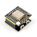
- Based on the ESP8266 WiFi microcontroller
- Integrated 2.4GHz IEEE 802.11 b/g/n WiFi connectivity
- Can operate as a standalone microcontroller
- Compatible with the Arduino IDE
- Supports AP, Station, and AP + Station operating modes
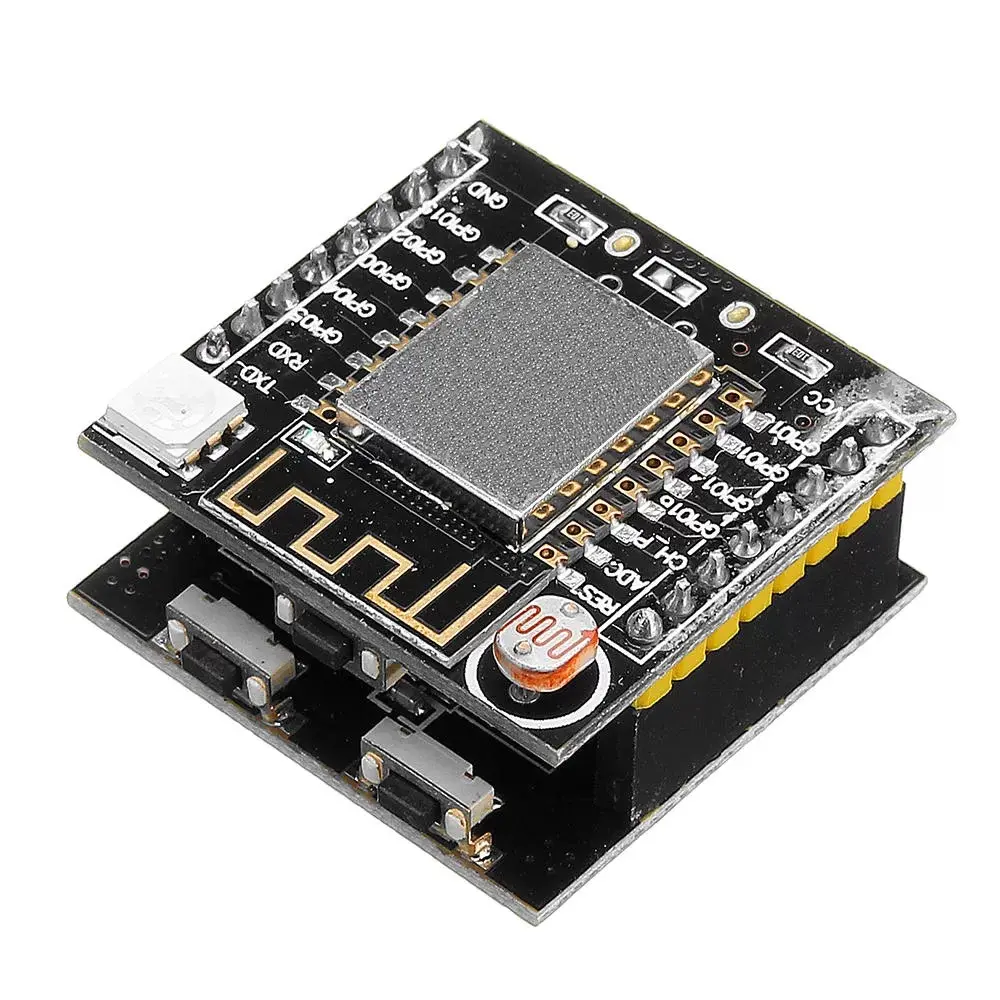
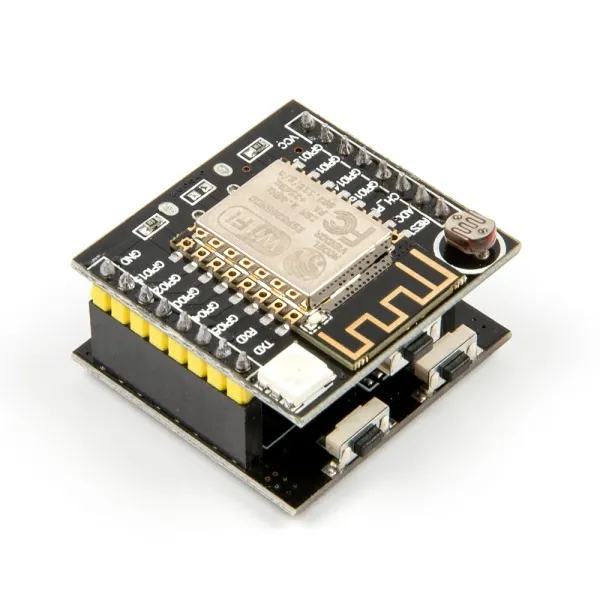
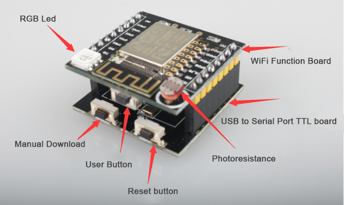
- Onboard light-dependent resistor (LDR)
- Programmable WS2812 RGB LED
- Onboard user push button
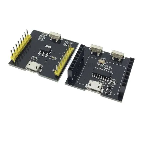
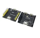
- Additional programming and reset buttons on the CH340 USB board
- CH340 USB-to-serial interface
- Micro USB connector for programming and power
- UART communication interface
- Multiple GPIO pins for connecting sensors and modules
- Compact and modular board design
- Supports low-power sleep modes
- Suitable for IoT and wireless embedded applications
Principle of Operation
The ESP8266 combines a microcontroller and a 2.4GHz WiFi transceiver in a single device. The onboard processor can execute user programs and control connected sensors, LEDs, and other electronic components through its GPIO pins.
The ESP8266 can connect directly to an existing WiFi router in Station (STA) mode, allowing the board to communicate with local network devices and internet services. It can also operate in Access Point (AP) mode, creating its own wireless network for other devices to connect to.
The onboard LDR detects changes in ambient light, while the programmable RGB LED can provide visual status information or lighting effects. The CH340 USB programming board converts USB communication from a computer into UART serial communication for programming the ESP8266.
Applications
- Internet of Things (IoT) projects
- Home automation systems
- Wireless sensor nodes
- WiFi-enabled lighting systems
- Environmental monitoring
- Smart home devices
- Wireless control systems
- Remote monitoring applications
- ESP8266 learning and development
Pinout
The Witty Cloud board provides GPIO, power, and UART connections through the ESP8266 module. The following are the commonly accessible connections:

| Pin | Function |
|---|---|
| 3V3 | 3.3V power supply |
| GND | Ground connection |
| TX | UART transmit pin |
| RX | UART receive pin |
| GPIO Pins | General-purpose input/output pins for external devices |
| ADC | Analog input, depending on the board configuration |
Note: The ESP8266 uses 3.3V logic. Do not apply 5V directly to the ESP8266 GPIO pins, as this may damage the module.
Programming with Arduino IDE
The Witty Cloud ESP8266 Development Board can be programmed using the Arduino IDE by installing the ESP8266 board package.
- Open the Arduino IDE.
- Go to File → Preferences.
- In the Additional Boards Manager URLs field, add the following address:
https://arduino.esp8266.com/stable/package_esp8266com_index.json
Go to Tools → Board → Boards Manager.- Search for ESP8266.
- Install the ESP8266 by ESP8266 Community package.
- Select an appropriate ESP8266 board configuration.
- Connect the CH340 USB programming board using a Micro USB cable.
- Select the correct serial port and upload the program.
Specifications
| Microcontroller | ESP8266 |
|---|---|
| WiFi Standard | IEEE 802.11 b/g/n |
| WiFi Frequency | 2.4GHz |
| Logic Level | 3.3V |
| Programming Interface | UART through CH340 USB-to-Serial Converter |
| USB Connector | Micro USB |
| Operating Modes | AP / STA / AP + STA |
| Onboard Light Sensor | LDR |
| Onboard RGB LED | WS2812 Programmable RGB LED |
| User Input | Onboard Push Buttons |
| Interfaces | GPIO, UART, WiFi, Analog Input |
| Power Supply | USB or regulated 3.3V supply, depending on the board connection |
Features
- Based on the ESP8266 WiFi microcontroller
- Integrated 2.4GHz IEEE 802.11 b/g/n WiFi connectivity
- Can operate as a standalone microcontroller
- Compatible with the Arduino IDE
- Supports AP, Station, and AP + Station operating modes
- Onboard light-dependent resistor (LDR)
- Programmable WS2812 RGB LED
- Onboard user push button
- Additional programming and reset buttons on the CH340 USB board
- CH340 USB-to-serial interface
- Micro USB connector for programming and power
- UART communication interface
- Multiple GPIO pins for connecting sensors and modules
- Compact and modular board design
- Supports low-power sleep modes
- Suitable for IoT and wireless embedded applications
Principle of Operation
The ESP8266 combines a microcontroller and a 2.4GHz WiFi transceiver in a single device. The onboard processor can execute user programs and control connected sensors, LEDs, and other electronic components through its GPIO pins.
The ESP8266 can connect directly to an existing WiFi router in Station (STA) mode, allowing the board to communicate with local network devices and internet services. It can also operate in Access Point (AP) mode, creating its own wireless network for other devices to connect to.
The onboard LDR detects changes in ambient light, while the programmable RGB LED can provide visual status information or lighting effects. The CH340 USB programming board converts USB communication from a computer into UART serial communication for programming the ESP8266.
Applications
- Internet of Things (IoT) projects
- Home automation systems
- Wireless sensor nodes
- WiFi-enabled lighting systems
- Environmental monitoring
- Smart home devices
- Wireless control systems
- Remote monitoring applications
- ESP8266 learning and development
Pinout
The Witty Cloud board provides GPIO, power, and UART connections through the ESP8266 module. The following are the commonly accessible connections:
| Pin | Function |
|---|---|
| 3V3 | 3.3V power supply |
| GND | Ground connection |
| TX | UART transmit pin |
| RX | UART receive pin |
| GPIO Pins | General-purpose input/output pins for external devices |
| ADC | Analog input, depending on the board configuration |
Note: The ESP8266 uses 3.3V logic. Do not apply 5V directly to the ESP8266 GPIO pins, as this may damage the module.
Programming with Arduino IDE
The Witty Cloud ESP8266 Development Board can be programmed using the Arduino IDE by installing the ESP8266 board package.
- Open the Arduino IDE.
- Go to File → Preferences.
- In the Additional Boards Manager URLs field, add the following address:
https://arduino.esp8266.com/stable/package_esp8266com_index.json
Go to Tools → Board → Boards Manager.- Search for ESP8266.
- Install the ESP8266 by ESP8266 Community package.
- Select an appropriate ESP8266 board configuration.
- Connect the CH340 USB programming board using a Micro USB cable.
- Select the correct serial port and upload the program.
Specifications
| Microcontroller | ESP8266 |
|---|---|
| WiFi Standard | IEEE 802.11 b/g/n |
| WiFi Frequency | 2.4GHz |
| Logic Level | 3.3V |
| Programming Interface | UART through CH340 USB-to-Serial Converter |
| USB Connector | Micro USB |
| Operating Modes | AP / STA / AP + STA |
| Onboard Light Sensor | LDR |
| Onboard RGB LED | WS2812 Programmable RGB LED |
| User Input | Onboard Push Buttons |
| Interfaces | GPIO, UART, WiFi, Analog Input |
| Power Supply | USB or regulated 3.3V supply, depending on the board connection |