
Features:
- Compatible with ESP-32F, ESP32, and ESP-WROOM-32 modules
- Standard 2.54 mm pin pitch for breadboard compatibility
- Requires only 4 connections for basic operation
- Built-in RESET and IO0 (Flash) buttons
- Easy firmware upload with download mode support
- Simplifies debugging and development workflow
- Compact and easy-to-use design
Specifications:
- Compatibility: ESP-32F / ESP32 / ESP-WROOM-32
- Pin Pitch: 2.54 mm
- Operating Voltage: 3.3V
- Interface: UART (TX/RX)
- Buttons: RESET, IO0 (Flash/Boot)
- Form Factor: Breadboard compatible
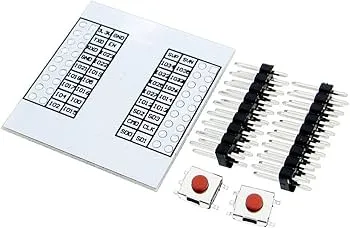
Pinout of the Module:
The breakout board exposes key ESP32 pins for easy access and connection.

- 3.3V: Power supply input
- GND: Ground
- TXD: Connect to RX of USB-to-Serial adapter
- RXD: Connect to TX of USB-to-Serial adapter
- EN: Enable pin (requires pull-up resistor)
- IO0: Boot mode selection (LOW for flashing)
Applications:
- ESP32 prototyping and development
- IoT and wireless communication projects
- Firmware flashing and debugging
- Embedded systems testing
- Educational electronics projects
Circuit:
Insert the ESP32 module into the adapter and connect it to a USB-to-Serial converter using TX, RX, 3.3V, and GND. For stable operation, connect a pull-up resistor (recommended 12KΩ) between EN and 3.3V. Use the onboard IO0 and RESET buttons to control boot and flashing modes.
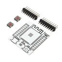
Connecting with the ESP32 Adapter for the First Time:
- Mount the ESP32 module onto the adapter board and solder it.
- Connect TX → RX and RX → TX to USB-to-Serial adapter
- Connect 3.3V and GND
- Add a 12KΩ pull-up resistor between EN and 3.3V
- Press IO0 and then RESET to enter download mode
- Upload your firmware using Arduino IDE
Code Example (ESP32 Blink):
 #define LED_PIN 2

void setup() {
pinMode(LED_PIN, OUTPUT);
}

void loop() {
digitalWrite(LED_PIN, HIGH);
delay(500);
digitalWrite(LED_PIN, LOW);
delay(500);
}
Arduino IDE Setup (ESP32):
Install Arduino IDE:
Add ESP32 Board Support:
- Open Arduino IDE → File → Preferences
- Add this URL:
https://dl.espressif.com/dl/package_esp32_index.json
- Go to Tools → Board → Boards Manager
- Search "ESP32" and install
Upload Code:
- Select "ESP32 Dev Module"
- Choose correct COM port
- Hold IO0 if required, then click Upload
Important Notes:
- Recommended pull-up resistor on EN: 4.7KΩ – 20KΩ (12KΩ typical)
- Ensure TX/RX are cross-connected
- Use only 3.3V power supply
- ESP32 module is not included
Resources:
Features:
- Compatible with ESP-32F, ESP32, and ESP-WROOM-32 modules
- Standard 2.54 mm pin pitch for breadboard compatibility
- Requires only 4 connections for basic operation
- Built-in RESET and IO0 (Flash) buttons
- Easy firmware upload with download mode support
- Simplifies debugging and development workflow
- Compact and easy-to-use design
Specifications:
- Compatibility: ESP-32F / ESP32 / ESP-WROOM-32
- Pin Pitch: 2.54 mm
- Operating Voltage: 3.3V
- Interface: UART (TX/RX)
- Buttons: RESET, IO0 (Flash/Boot)
- Form Factor: Breadboard compatible
Pinout of the Module:
The breakout board exposes key ESP32 pins for easy access and connection.
- 3.3V: Power supply input
- GND: Ground
- TXD: Connect to RX of USB-to-Serial adapter
- RXD: Connect to TX of USB-to-Serial adapter
- EN: Enable pin (requires pull-up resistor)
- IO0: Boot mode selection (LOW for flashing)
Applications:
- ESP32 prototyping and development
- IoT and wireless communication projects
- Firmware flashing and debugging
- Embedded systems testing
- Educational electronics projects
Circuit:
Insert the ESP32 module into the adapter and connect it to a USB-to-Serial converter using TX, RX, 3.3V, and GND. For stable operation, connect a pull-up resistor (recommended 12KΩ) between EN and 3.3V. Use the onboard IO0 and RESET buttons to control boot and flashing modes.
Connecting with the ESP32 Adapter for the First Time:
- Mount the ESP32 module onto the adapter board and solder it.
- Connect TX → RX and RX → TX to USB-to-Serial adapter
- Connect 3.3V and GND
- Add a 12KΩ pull-up resistor between EN and 3.3V
- Press IO0 and then RESET to enter download mode
- Upload your firmware using Arduino IDE
Code Example (ESP32 Blink):
 #define LED_PIN 2

void setup() {
pinMode(LED_PIN, OUTPUT);
}

void loop() {
digitalWrite(LED_PIN, HIGH);
delay(500);
digitalWrite(LED_PIN, LOW);
delay(500);
}
Arduino IDE Setup (ESP32):
Install Arduino IDE:
Add ESP32 Board Support:
- Open Arduino IDE → File → Preferences
- Add this URL:
https://dl.espressif.com/dl/package_esp32_index.json
- Go to Tools → Board → Boards Manager
- Search "ESP32" and install
Upload Code:
- Select "ESP32 Dev Module"
- Choose correct COM port
- Hold IO0 if required, then click Upload
Important Notes:
- Recommended pull-up resistor on EN: 4.7KΩ – 20KΩ (12KΩ typical)
- Ensure TX/RX are cross-connected
- Use only 3.3V power supply
- ESP32 module is not included