Features
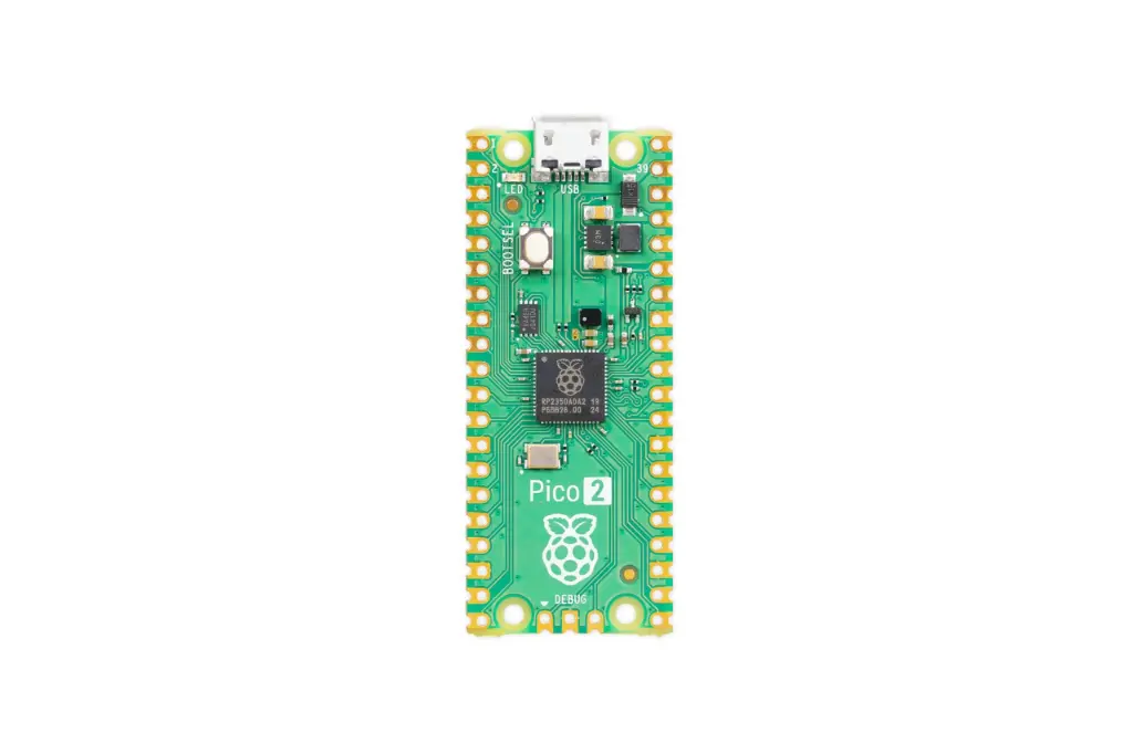
- Official Raspberry Pi Pico 2 microcontroller development board.
- Powered by the advanced RP2350A microcontroller.
- Selectable dual-core processor architecture:
- Dual ARM Cortex-M33 cores
- Dual RISC-V Hazard3 cores
- High-performance operation up to 150MHz system clock.
- 520KB SRAM and 4MB QSPI Flash memory.
- Advanced security features including ARM TrustZone and secure boot support.
- USB Micro-B connector for power, programming, and data transfer.
- Supports drag-and-drop programming through USB Mass Storage mode.
- Compatible with MicroPython, CircuitPython, C, and C++.
- Arduino IDE support planned.
- 26 multifunction 3.3V GPIO pins.
- Supports ADC, PWM, UART, SPI, I2C, and PIO interfaces.
- Breadboard-friendly 40-pin DIP design.
- Castellated PCB edges for direct SMD mounting.
- Low-power operation suitable for battery-powered projects.
- Wide operating temperature range for embedded applications.
Principle of Operation
The Raspberry Pi Pico 2 operates as a standalone microcontroller board where the RP2350A processor executes firmware stored in the onboard QSPI flash memory. The microcontroller manages connected sensors, actuators, communication devices, and other electronic peripherals through its programmable GPIO and hardware interfaces.
Programs can be uploaded through the USB interface using drag-and-drop programming mode or through supported development environments. The integrated peripherals allow the Pico 2 to perform real-time control tasks, process sensor data, communicate with external devices, and execute embedded applications without requiring a full operating system.
Applications
- Embedded systems development
- Robotics and automation projects
- IoT devices and smart controllers
- Sensor data acquisition systems
- Industrial control prototypes
- Motor and actuator control
- Wearable electronics
- Custom PCB development
- Educational electronics projects
- Rapid prototyping
- Real-time control applications
Pinout
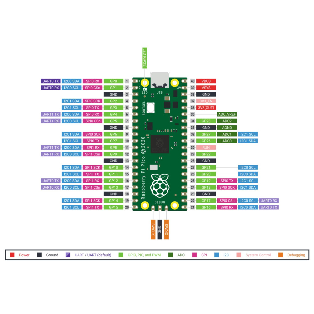
| Pin Group | Function |
|---|---|
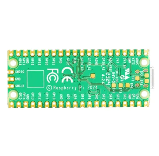
| GPIO0 - GPIO28 | 3.3V Multifunction GPIO |
| ADC0 - ADC2 | 12-bit Analog Inputs |
| GP25 | Programmable Onboard LED |
| UART0 / UART1 | Serial Communication |
| SPI0 / SPI1 | SPI Communication |
| I2C0 / I2C1 | I2C Communication |
| SWD | 3-pin ARM Serial Wire Debug Interface |
| VSYS | Main System Power Input |
| 3V3 | Regulated 3.3V Output |
| GND | Ground Connection |
Wiring
The Raspberry Pi Pico 2 can be powered and programmed through the USB Micro-B connector or supplied externally through the VSYS pin. External sensors and modules can be connected directly to the GPIO pins using standard jumper wires or breadboards.
Specifications
| Product Type | Microcontroller Development Board |
| Brand | Raspberry Pi |
| Model | Pico 2 |
| Microcontroller | RP2350A |
| CPU Architecture | Dual ARM Cortex-M33 or Dual RISC-V Hazard3 |
| System Clock | Up to 150MHz |
| SRAM | 520KB |
| Flash Memory | 4MB QSPI Flash (XIP v2) |
| Security Features | ARM TrustZone, Secure Boot Support, SHA-256 Accelerator |
| USB Interface | USB 1.1 Host and Device |
| USB Programming | USB Mass Storage Boot Mode |
| GPIO | 26 Multifunction 3.3V GPIO |
| Analog Inputs | 3 × 12-bit ADC (up to 500Ksps) |
| Temperature Sensor | Integrated On-chip Temperature Sensor |
| Communication Interfaces | 2 × UART, 2 × SPI, 2 × I2C |
| PWM | 16 PWM Channels |
| PIO | 3 PIO Blocks with 12 PIO Pins |
| Debug Interface | 3-pin ARM SWD |
| Onboard LED | Programmable LED on GP25 |
| Power Supply | USB Power, External 2–5V DC, Battery Supported |
| Form Factor | 40-pin DIP Breadboard Compatible |
| PCB Thickness | 1mm |
| Operating Temperature | -20°C to +85°C |
| Dimensions | 51mm × 21mm × 1mm |
| Operating Systems | Windows, macOS, Linux, Raspberry Pi OS |
Library Required
The required libraries depend on the programming environment and connected peripherals.
- MicroPython: Built-in MicroPython libraries (no additional installation required).
- C/C++ SDK: Raspberry Pi Pico SDK.
- CircuitPython: CircuitPython libraries from Adafruit.
- Arduino IDE: Raspberry Pi Pico board support package.
Installing CircuitPython on Raspberry Pi Pico 2
CircuitPython provides an easy way to program the Raspberry Pi Pico 2 using Python. The setup only requires installing the CircuitPython firmware and copying your code files directly to the board.
1. Download CircuitPython Firmware
Download the latest CircuitPython firmware for Raspberry Pi Pico 2 from the official CircuitPython website:
Raspberry Pi Pico 2 CircuitPython Firmware
2. Install CircuitPython
Disconnect the Pico 2 from USB, then press and hold the BOOTSEL button while connecting it to your computer using a USB data cable.
A new USB drive named RPI-RP2 will appear. Copy the downloaded .UF2 CircuitPython firmware file into this drive.
After the installation is completed, the board will restart automatically and a new drive named CIRCUITPY will appear.
3. Add Libraries
For basic Pico 2 functions, no additional libraries are required. For sensors, displays, and external modules, download the required libraries from the Adafruit CircuitPython Library Bundle and copy them into the lib folder on the CIRCUITPY drive.
Adafruit CircuitPython Library Bundle
4. Write Your First Program
Create a file named code.py on the CIRCUITPY drive. The Pico 2 will automatically run this file whenever it is powered on or reset.
You can edit programs using editors such as Thonny, Mu Editor, or any text editor.
Example Arduino Code
import time
import board
import digitalio

# Configure onboard LED
led = digitalio.DigitalInOut(board.LED)
led.direction = digitalio.Direction.OUTPUT

# Blink LED
while True:
 led.value = True # Turn LED ON
 time.sleep(1)

 led.value = False # Turn LED OFF
 time.sleep(1)
How it works:
board.LED selects the built-in LED on the Pico 2. digitalio controls the GPIO pin. The loop turns the LED ON for 1 second and OFF for 1 second. CircuitPython automatically runs code.py every time the Pico 2 starts. After saving the file, the Pico 2 will restart automatically and the LED will begin blinking.
Resources
- Raspberry Pi Pico 2 Documentation:
https://www.raspberrypi.com/documentation/microcontrollers/pico-series.html - Raspberry Pi Pico SDK:
https://github.com/raspberrypi/pico-sdk - MicroPython for Raspberry Pi Pico:
https://micropython.org/download/RPI_PICO2/ - Raspberry Pi Official Website:
https://www.raspberrypi.com/ - Arduino IDE:
https://www.arduino.cc/en/software - CircuitPython
Adafruit CircuitPython Installation Guide
Official CircuitPython Website
Features
- Official Raspberry Pi Pico 2 microcontroller development board.
- Powered by the advanced RP2350A microcontroller.
- Selectable dual-core processor architecture:
- Dual ARM Cortex-M33 cores
- Dual RISC-V Hazard3 cores
- High-performance operation up to 150MHz system clock.
- 520KB SRAM and 4MB QSPI Flash memory.
- Advanced security features including ARM TrustZone and secure boot support.
- USB Micro-B connector for power, programming, and data transfer.
- Supports drag-and-drop programming through USB Mass Storage mode.
- Compatible with MicroPython, CircuitPython, C, and C++.
- Arduino IDE support planned.
- 26 multifunction 3.3V GPIO pins.
- Supports ADC, PWM, UART, SPI, I2C, and PIO interfaces.
- Breadboard-friendly 40-pin DIP design.
- Castellated PCB edges for direct SMD mounting.
- Low-power operation suitable for battery-powered projects.
- Wide operating temperature range for embedded applications.
Principle of Operation
The Raspberry Pi Pico 2 operates as a standalone microcontroller board where the RP2350A processor executes firmware stored in the onboard QSPI flash memory. The microcontroller manages connected sensors, actuators, communication devices, and other electronic peripherals through its programmable GPIO and hardware interfaces.
Programs can be uploaded through the USB interface using drag-and-drop programming mode or through supported development environments. The integrated peripherals allow the Pico 2 to perform real-time control tasks, process sensor data, communicate with external devices, and execute embedded applications without requiring a full operating system.
Applications
- Embedded systems development
- Robotics and automation projects
- IoT devices and smart controllers
- Sensor data acquisition systems
- Industrial control prototypes
- Motor and actuator control
- Wearable electronics
- Custom PCB development
- Educational electronics projects
- Rapid prototyping
- Real-time control applications
Pinout
| Pin Group | Function |
|---|---|
| GPIO0 - GPIO28 | 3.3V Multifunction GPIO |
| ADC0 - ADC2 | 12-bit Analog Inputs |
| GP25 | Programmable Onboard LED |
| UART0 / UART1 | Serial Communication |
| SPI0 / SPI1 | SPI Communication |
| I2C0 / I2C1 | I2C Communication |
| SWD | 3-pin ARM Serial Wire Debug Interface |
| VSYS | Main System Power Input |
| 3V3 | Regulated 3.3V Output |
| GND | Ground Connection |
Wiring
The Raspberry Pi Pico 2 can be powered and programmed through the USB Micro-B connector or supplied externally through the VSYS pin. External sensors and modules can be connected directly to the GPIO pins using standard jumper wires or breadboards.
Specifications
| Product Type | Microcontroller Development Board |
| Brand | Raspberry Pi |
| Model | Pico 2 |
| Microcontroller | RP2350A |
| CPU Architecture | Dual ARM Cortex-M33 or Dual RISC-V Hazard3 |
| System Clock | Up to 150MHz |
| SRAM | 520KB |
| Flash Memory | 4MB QSPI Flash (XIP v2) |
| Security Features | ARM TrustZone, Secure Boot Support, SHA-256 Accelerator |
| USB Interface | USB 1.1 Host and Device |
| USB Programming | USB Mass Storage Boot Mode |
| GPIO | 26 Multifunction 3.3V GPIO |
| Analog Inputs | 3 × 12-bit ADC (up to 500Ksps) |
| Temperature Sensor | Integrated On-chip Temperature Sensor |
| Communication Interfaces | 2 × UART, 2 × SPI, 2 × I2C |
| PWM | 16 PWM Channels |
| PIO | 3 PIO Blocks with 12 PIO Pins |
| Debug Interface | 3-pin ARM SWD |
| Onboard LED | Programmable LED on GP25 |
| Power Supply | USB Power, External 2–5V DC, Battery Supported |
| Form Factor | 40-pin DIP Breadboard Compatible |
| PCB Thickness | 1mm |
| Operating Temperature | -20°C to +85°C |
| Dimensions | 51mm × 21mm × 1mm |
| Operating Systems | Windows, macOS, Linux, Raspberry Pi OS |
Library Required
The required libraries depend on the programming environment and connected peripherals.
- MicroPython: Built-in MicroPython libraries (no additional installation required).
- C/C++ SDK: Raspberry Pi Pico SDK.
- CircuitPython: CircuitPython libraries from Adafruit.
- Arduino IDE: Raspberry Pi Pico board support package.
Installing CircuitPython on Raspberry Pi Pico 2
CircuitPython provides an easy way to program the Raspberry Pi Pico 2 using Python. The setup only requires installing the CircuitPython firmware and copying your code files directly to the board.
1. Download CircuitPython Firmware
Download the latest CircuitPython firmware for Raspberry Pi Pico 2 from the official CircuitPython website:
Raspberry Pi Pico 2 CircuitPython Firmware
2. Install CircuitPython
Disconnect the Pico 2 from USB, then press and hold the BOOTSEL button while connecting it to your computer using a USB data cable.
A new USB drive named RPI-RP2 will appear. Copy the downloaded .UF2 CircuitPython firmware file into this drive.
After the installation is completed, the board will restart automatically and a new drive named CIRCUITPY will appear.
3. Add Libraries
For basic Pico 2 functions, no additional libraries are required. For sensors, displays, and external modules, download the required libraries from the Adafruit CircuitPython Library Bundle and copy them into the lib folder on the CIRCUITPY drive.
Adafruit CircuitPython Library Bundle
4. Write Your First Program
Create a file named code.py on the CIRCUITPY drive. The Pico 2 will automatically run this file whenever it is powered on or reset.
You can edit programs using editors such as Thonny, Mu Editor, or any text editor.
Example Arduino Code
import time
import board
import digitalio

# Configure onboard LED
led = digitalio.DigitalInOut(board.LED)
led.direction = digitalio.Direction.OUTPUT

# Blink LED
while True:
 led.value = True # Turn LED ON
 time.sleep(1)

 led.value = False # Turn LED OFF
 time.sleep(1)
How it works:
board.LED selects the built-in LED on the Pico 2. digitalio controls the GPIO pin. The loop turns the LED ON for 1 second and OFF for 1 second. CircuitPython automatically runs code.py every time the Pico 2 starts. After saving the file, the Pico 2 will restart automatically and the LED will begin blinking.
Resources
- Raspberry Pi Pico 2 Documentation:
https://www.raspberrypi.com/documentation/microcontrollers/pico-series.html - Raspberry Pi Pico SDK:
https://github.com/raspberrypi/pico-sdk - MicroPython for Raspberry Pi Pico:
https://micropython.org/download/RPI_PICO2/ - Raspberry Pi Official Website:
https://www.raspberrypi.com/ - Arduino IDE:
https://www.arduino.cc/en/software - CircuitPython
Adafruit CircuitPython Installation Guide
Official CircuitPython Website