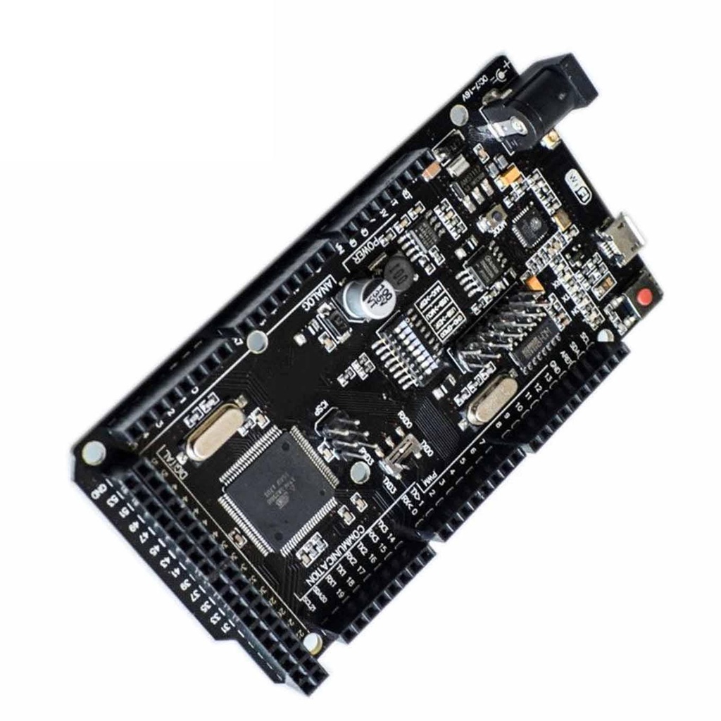
- All products
- Development Boards
- Arduino
- Mega2560 + WiFi R3 ATMEGA2560+ESP8266 32MB Memory USB-TTL CH340g
- Arduino
Board Layout:
- Same dimensions as the original Arduino Mega
- ATmega2560 shifted to the right, ESP8266 on the left
- Micro USB connector (Type-B to Micro-B) located above the ESP8266
- Communication through CH340G and 8-pin DIP switch
DIP Switch Configuration Table:
| Mode | 1 | 2 | 3 | 4 | 5 | 6 | 7 | 8 |
|---|---|---|---|---|---|---|---|---|
| CH340 → ESP8266 (Upload Sketch) | OFF | OFF | OFF | OFF | ON | ON | ON | No Use |
| CH340 → ESP8266 (Connect) | OFF | OFF | OFF | OFF | ON | ON | OFF | No Use |
| CH340 → ATmega2560 (Upload Sketch) | OFF | OFF | ON | ON | OFF | OFF | OFF | No Use |
| CH340 → Mega2560 + COM3 ↔ ESP8266 | ON | ON | ON | ON | OFF | OFF | OFF | No Use |
| Mega2560 + ESP8266 | ON | ON | OFF | OFF | OFF | OFF | OFF | No Use |
| All modules independent | OFF | OFF | OFF | OFF | OFF | OFF | OFF | No Use |
Driver Installation (CH340):
- Download the Windows CH340 Driver
- Unzip the downloaded file
- Run the installer
- Open Arduino IDE → Tools → Port and select the COM port that appears (varies per system)
Board Setup in Arduino IDE:
- Go to File → Preferences → Additional Board Manager URLs
- Paste:
http://arduino.esp8266.com/stable/package_esp8266com_index.jsonand click OK - Navigate to Tools → Board → Board Manager
- Search for "ESP" and install it
DIP Switch Setting Example (USB → ATmega2560):
| Mode | 1 | 2 | 3 | 4 | 5 | 6 | 7 | 8 | RXD/TXD |
|---|---|---|---|---|---|---|---|---|---|
| USB → ATmega2560 | --- | --- | ON | ON | --- | --- | --- | 0 | RXD/TXD |
Flashing and Testing:
- Connect the board to your PC via USB
- Open Arduino IDE
- Select Tools → Board → Arduino / Genuino Mega or Mega 2560
- Select the COM port from Tools → Port
- Open test sketch: File → Sketch Folder → TEST_MEGA
- Upload the sketch via Sketch → Upload
Serial Monitor Test Commands:
- Baud Rate: 115200
- Send
a– LED will blink for 20 seconds - Send
b– Display available memory: SRAM and EEPROM - Send
c– Run output pin test (Pins 0, 1, 13 may show faults due to UART and onboard LED)
Note: After all checks are completed, disconnect the board from the USB port.