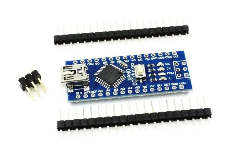
Features:
- Small size and compact design (45mm x 18mm)
- 14 digital input/output pins
- 8 analog inputs
- 16MHz clock speed
- 32KB flash memory for storing code
- 2KB SRAM for storing variables
- 1KB EEPROM for storing data
- Built-in USB port for easy programming and debugging
- Compatible with Arduino IDE
- CH340 USB-to-serial chip for serial communication
- Power jack for external power supply
- Supports I2C, SPI, and UART communication protocols
- Breadboard-friendly design for easy prototyping and development
- Can be powered via USB or external power supply
- Unsoldered version for greater customization and flexibility when assembling the board.
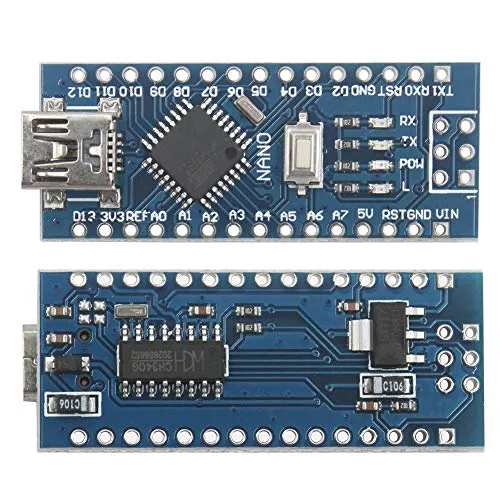
Principle of Work:
The Arduino Nano v3 ATMEGA328P - CH340 board is based on the ATmega328P microcontroller, which is the board's brain. The microcontroller is responsible for controlling the inputs and outputs of the board, executing the program code, and communicating with external devices via serial communication or other protocols. The CH340 USB-to-serial chip on the board is used for serial communication with a computer, allowing for easy programming and debugging using the Arduino IDE. When the board is connected to a computer via USB, the CH340 chip creates a virtual serial port on the computer. The Arduino IDE uses this serial port to upload the program code to the microcontroller on the board. When you write a program using the Arduino IDE, the code is compiled and uploaded to the board via the USB port. The program code is stored in the flash memory of the microcontroller. When the board is powered on or reset, the microcontroller executes the program code, controlling the inputs and outputs of the board based on the logic of the program. The Arduino IDE includes a range of libraries and example codes that can be used to get started with programming the board. The IDE also includes a serial monitor, which allows you to send and receive data between the board and the computer via the serial port.
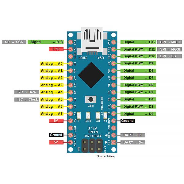
Pinout of the Board:
| Pin | Name | Function |
|---|---|---|
| 1 | D13 | Digital output (SPI clock) |
| 2 | D12 | Digital output (SPI MISO) |
| 3 | D11 | Digital output (SPI MOSI) |
| 4 | D10 | Digital output (SPI chip select) |
| 5 | D9 | Digital output (PWM) |
| 6 | D8 | Digital output (PWM) |
| 7 | D7 | Digital output |
| 8 | D6 | Digital output (PWM) |
| 9 | D5 | Digital output (PWM) |
| 10 | D4 | Digital output |
| 11 | D3 | Digital output (PWM) |
| 12 | D2 | Digital output |
| 13 | D1 | Digital output |
| 14 | D0 | Digital input/output |
| 15 | AREF | Analog reference voltage input |
| 16 | A0 | Analog input |
| 17 | A1 | Analog input |
| 18 | A2 | Analog input |
| 19 | A3 | Analog input |
| 20 | A4 | Analog input/output (I2C SDA) |
| 21 | A5 | Analog input/output (I2C SCL) |
| 22 | RESET | Reset |
| 23 | 5V | Power supply (5V) |
| 24 | GND | Ground |
| 25 | Vin | Power supply input (7-12V) |
| 26 | NC | Not connected |
Applications:
- Robotics: The board can be used in various robotics applications, such as controlling motors and sensors.
- Home automation: The board can be used to control home appliances and lights using relays and other electronic components.
- IoT projects: The board can be used to build various IoT projects such as weather stations, smart locks, and other connected devices.
- Wearables: Due to its small size, the board can be used in wearable technology applications such as smartwatches and fitness trackers.
- Education: The board is commonly used in educational settings to teach basic electronics and programming concepts.
- DIY projects: The board can be used in various DIY projects such as building a remote-controlled car or a home automation system.
- Data logging: The board can be used to log data from sensors and other inputs to an SD card or a computer.
Circuit:
No need for a circuit we will use the onboard LED on Pin 13.
Library:
Steps to download and use the Arduino Nano v3 ATmega328P with CH340 for the first time:
- Download and install the Arduino IDE: Go to the official Arduino website (https://www.arduino.cc/en/software) and download the latest version of the Arduino IDE for your operating system. Follow the installation instructions provided.
- Before Connecting the board to your computer: Connect your Arduino Nano board to your computer using a USB cable.
- Go to the official website of the CH340 driver provider: You can download the CH340 driver from various sources, but it's recommended to download it from the official website of the provider. One such provider is WCH (http://www.wch.cn/download/CH341SER_ZIP.html).
- Download the driver: On the website, find the appropriate driver for your operating system and click on the download link. The driver is usually available in the form of a ZIP file.
- Extract the ZIP file: After the download is complete, extract the ZIP file to a folder on your computer.
- Install the driver: Double-click on the extracted file and follow the installation instructions provided. The installation process may vary depending on your operating system.
- Connect your device: Once the driver is installed, connect your device (Arduino board) to your computer using a USB cable. The driver should be automatically detected and installed by your operating system.
- Select the board type: Open the Arduino IDE, go to the Tools menu, and select the Board type as "Arduino Nano". Then, select the Processor as "ATmega328P".
- Select the serial port: Go to the Tools menu and select the Serial port that corresponds to the USB port your board is connected to.
- Upload a sketch: Open an example sketch or write your own code, and click the "Upload" button to upload the sketch to the board. The onboard LED should blink once the upload is complete.
- Verify the output: Open the Serial Monitor (Tools menu > Serial Monitor), and set the baud rate to 9600. You should see the output of your sketch printed in the Serial Monitor.
That's it! You have successfully downloaded and used the Arduino Nano v3 ATmega328P with CH340 for the first time.
Code:
an example sketch that you can use to control the onboard LED in Arduino Nano using the Serial Monitor:
void setup() {
 pinMode(LED_BUILTIN, OUTPUT); // set the LED pin as output
 Serial.begin(9600); // initialize the Serial Monitor
}
void loop() {
 if (Serial.available()) { // if there's data available in Serial Monitor
 char command = Serial.read(); // read the incoming command
 if (command == '1') { // if the command is '1'
 digitalWrite(LED_BUILTIN, HIGH); // turn on the LED
 Serial.println("LED turned on"); // print message to Serial Monitor
 }
 else if (command == '0') { // if the command is '0'
 digitalWrite(LED_BUILTIN, LOW); // turn off the LED
 Serial.println("LED turned off"); // print message to Serial Monitor
 }
 }
}
- Upload the sketch to the Arduino Nano using the Arduino IDE.
- Open the Serial Monitor (Tools menu > Serial Monitor).
- Set the baud rate to 9600.
- Type '1' and press Enter to turn on the LED. Type '0' and press Enter to turn off the LED. You should see the messages "LED turned on" or "LED turned off" printed in the Serial Monitor, and the LED on the Arduino Nano board should turn on or off accordingly.
Technical Details:
- Microcontroller: ATmega328P
- Operating Voltage: 5V
- Input Voltage (recommended): 7-12V
- Input Voltage (limit): 6-20V
- Digital I/O Pins: 14 (of which 6 provide PWM output)
- Analog Input Pins: 8
- DC Current per I/O Pin: 20 mA
- DC Current for 3.3V Pin: 50 mA
- Flash Memory: 32 KB (ATmega328P) of which 2 KB used by bootloader
- SRAM: 2 KB (ATmega328P)
- EEPROM: 1 KB (ATmega328P)
- Clock Speed: 16 MHz
- USB to serial converter: CH340G
Resources:
Features:
- Small size and compact design (45mm x 18mm)
- 14 digital input/output pins
- 8 analog inputs
- 16MHz clock speed
- 32KB flash memory for storing code
- 2KB SRAM for storing variables
- 1KB EEPROM for storing data
- Built-in USB port for easy programming and debugging
- Compatible with Arduino IDE
- CH340 USB-to-serial chip for serial communication
- Power jack for external power supply
- Supports I2C, SPI, and UART communication protocols
- Breadboard-friendly design for easy prototyping and development
- Can be powered via USB or external power supply
- Unsoldered version for greater customization and flexibility when assembling the board.
Principle of Work:
The Arduino Nano v3 ATMEGA328P - CH340 board is based on the ATmega328P microcontroller, which is the board's brain. The microcontroller is responsible for controlling the inputs and outputs of the board, executing the program code, and communicating with external devices via serial communication or other protocols. The CH340 USB-to-serial chip on the board is used for serial communication with a computer, allowing for easy programming and debugging using the Arduino IDE. When the board is connected to a computer via USB, the CH340 chip creates a virtual serial port on the computer. The Arduino IDE uses this serial port to upload the program code to the microcontroller on the board. When you write a program using the Arduino IDE, the code is compiled and uploaded to the board via the USB port. The program code is stored in the flash memory of the microcontroller. When the board is powered on or reset, the microcontroller executes the program code, controlling the inputs and outputs of the board based on the logic of the program. The Arduino IDE includes a range of libraries and example codes that can be used to get started with programming the board. The IDE also includes a serial monitor, which allows you to send and receive data between the board and the computer via the serial port.
Pinout of the Board:
| Pin | Name | Function |
|---|---|---|
| 1 | D13 | Digital output (SPI clock) |
| 2 | D12 | Digital output (SPI MISO) |
| 3 | D11 | Digital output (SPI MOSI) |
| 4 | D10 | Digital output (SPI chip select) |
| 5 | D9 | Digital output (PWM) |
| 6 | D8 | Digital output (PWM) |
| 7 | D7 | Digital output |
| 8 | D6 | Digital output (PWM) |
| 9 | D5 | Digital output (PWM) |
| 10 | D4 | Digital output |
| 11 | D3 | Digital output (PWM) |
| 12 | D2 | Digital output |
| 13 | D1 | Digital output |
| 14 | D0 | Digital input/output |
| 15 | AREF | Analog reference voltage input |
| 16 | A0 | Analog input |
| 17 | A1 | Analog input |
| 18 | A2 | Analog input |
| 19 | A3 | Analog input |
| 20 | A4 | Analog input/output (I2C SDA) |
| 21 | A5 | Analog input/output (I2C SCL) |
| 22 | RESET | Reset |
| 23 | 5V | Power supply (5V) |
| 24 | GND | Ground |
| 25 | Vin | Power supply input (7-12V) |
| 26 | NC | Not connected |
Applications:
- Robotics: The board can be used in various robotics applications, such as controlling motors and sensors.
- Home automation: The board can be used to control home appliances and lights using relays and other electronic components.
- IoT projects: The board can be used to build various IoT projects such as weather stations, smart locks, and other connected devices.
- Wearables: Due to its small size, the board can be used in wearable technology applications such as smartwatches and fitness trackers.
- Education: The board is commonly used in educational settings to teach basic electronics and programming concepts.
- DIY projects: The board can be used in various DIY projects such as building a remote-controlled car or a home automation system.
- Data logging: The board can be used to log data from sensors and other inputs to an SD card or a computer.
Circuit:
No need for a circuit we will use the onboard LED on Pin 13.
Library:
Steps to download and use the Arduino Nano v3 ATmega328P with CH340 for the first time:
- Download and install the Arduino IDE: Go to the official Arduino website (https://www.arduino.cc/en/software) and download the latest version of the Arduino IDE for your operating system. Follow the installation instructions provided.
- Before Connecting the board to your computer: Connect your Arduino Nano board to your computer using a USB cable.
- Go to the official website of the CH340 driver provider: You can download the CH340 driver from various sources, but it's recommended to download it from the official website of the provider. One such provider is WCH (http://www.wch.cn/download/CH341SER_ZIP.html).
- Download the driver: On the website, find the appropriate driver for your operating system and click on the download link. The driver is usually available in the form of a ZIP file.
- Extract the ZIP file: After the download is complete, extract the ZIP file to a folder on your computer.
- Install the driver: Double-click on the extracted file and follow the installation instructions provided. The installation process may vary depending on your operating system.
- Connect your device: Once the driver is installed, connect your device (Arduino board) to your computer using a USB cable. The driver should be automatically detected and installed by your operating system.
- Select the board type: Open the Arduino IDE, go to the Tools menu, and select the Board type as "Arduino Nano". Then, select the Processor as "ATmega328P".
- Select the serial port: Go to the Tools menu and select the Serial port that corresponds to the USB port your board is connected to.
- Upload a sketch: Open an example sketch or write your own code, and click the "Upload" button to upload the sketch to the board. The onboard LED should blink once the upload is complete.
- Verify the output: Open the Serial Monitor (Tools menu > Serial Monitor), and set the baud rate to 9600. You should see the output of your sketch printed in the Serial Monitor.
That's it! You have successfully downloaded and used the Arduino Nano v3 ATmega328P with CH340 for the first time.
Code:
an example sketch that you can use to control the onboard LED in Arduino Nano using the Serial Monitor:
void setup() {
 pinMode(LED_BUILTIN, OUTPUT); // set the LED pin as output
 Serial.begin(9600); // initialize the Serial Monitor
}
void loop() {
 if (Serial.available()) { // if there's data available in Serial Monitor
 char command = Serial.read(); // read the incoming command
 if (command == '1') { // if the command is '1'
 digitalWrite(LED_BUILTIN, HIGH); // turn on the LED
 Serial.println("LED turned on"); // print message to Serial Monitor
 }
 else if (command == '0') { // if the command is '0'
 digitalWrite(LED_BUILTIN, LOW); // turn off the LED
 Serial.println("LED turned off"); // print message to Serial Monitor
 }
 }
}
- Upload the sketch to the Arduino Nano using the Arduino IDE.
- Open the Serial Monitor (Tools menu > Serial Monitor).
- Set the baud rate to 9600.
- Type '1' and press Enter to turn on the LED. Type '0' and press Enter to turn off the LED. You should see the messages "LED turned on" or "LED turned off" printed in the Serial Monitor, and the LED on the Arduino Nano board should turn on or off accordingly.
Technical Details:
- Microcontroller: ATmega328P
- Operating Voltage: 5V
- Input Voltage (recommended): 7-12V
- Input Voltage (limit): 6-20V
- Digital I/O Pins: 14 (of which 6 provide PWM output)
- Analog Input Pins: 8
- DC Current per I/O Pin: 20 mA
- DC Current for 3.3V Pin: 50 mA
- Flash Memory: 32 KB (ATmega328P) of which 2 KB used by bootloader
- SRAM: 2 KB (ATmega328P)
- EEPROM: 1 KB (ATmega328P)
- Clock Speed: 16 MHz
- USB to serial converter: CH340G