Features
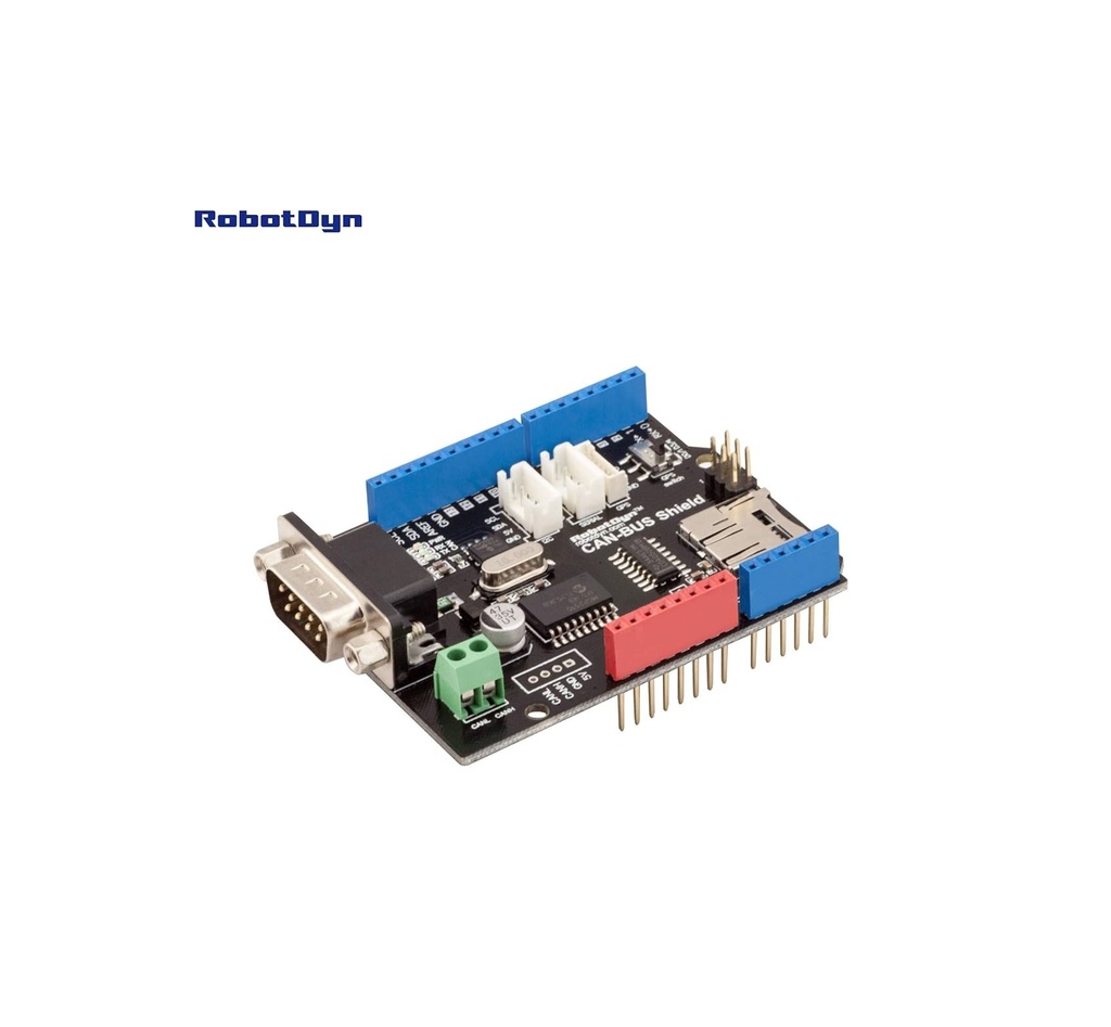
- CAN-BUS Connectivity: Allows Arduino boards to communicate with CAN networks used in automotive and industrial applications.
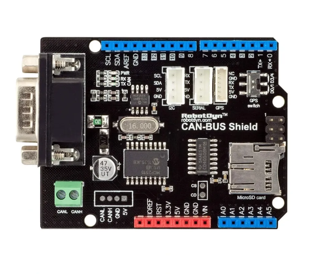
- MCP2515 CAN Controller: Provides the CAN protocol controller interface required for communication with the Arduino.
- MCP2551 CAN Transceiver: Provides the physical-layer interface between the CAN controller and CAN bus.
- Standard D-Sub Connector: Includes a 9-terminal D-Sub connector for convenient connection to compatible CAN/OBD-II wiring.
- Arduino IDE Compatible: Can be programmed using the Arduino IDE with compatible CAN-BUS libraries.
- Integrated MicroSD Interface: Allows CAN data and other project information to be stored on a MicroSD card.
- CD4050 Signal Buffer: The MicroSD interface uses CD4050 buffering for 5V-to-3.3V signal level conversion and improved signal stability.
- SPI Interface: The CAN controller and MicroSD interface use the Arduino SPI bus with separate chip-select control.
- Additional I2C Connector: Provides an expansion connection for compatible I2C devices.
- UART Connector: Provides a serial interface for additional UART peripherals.
- GPS Support: Includes a dedicated GPS connection and switching arrangement for UART communication.
- Fully Assembled: Supplied assembled and ready for integration into an Arduino project.
Principle of Operation
CAN communication is based on a multi-node bus in which multiple electronic devices can communicate using the same CANH and CANL differential signal lines. The Arduino communicates with the onboard MCP2515 CAN controller through the SPI interface.
The MCP2515 handles CAN protocol functions and converts the Arduino's commands into CAN frames. The MCP2551 transceiver then converts the controller's logic-level CAN signals into the differential electrical signals required by the physical CAN bus.
When receiving CAN messages, the MCP2551 receives the differential CANH/CANL signals and passes the corresponding data to the MCP2515. The Arduino can then read and process the received CAN frames through SPI.
Pin Configuration
The shield uses the Arduino SPI pins for communication with the onboard CAN controller and MicroSD card interface. Separate chip-select control allows the Arduino to select which SPI device is active.

| Arduino Pin | Function |
|---|---|
| D9 | MicroSD chip-select / data stream switching control |
| D10 | CAN controller chip-select |
| D11 | SPI MOSI |
| D12 | SPI MISO |
| D13 | SPI Clock (SCK) |
| D3 / D4 | Optional GPS UART connection |
| D0 / D1 | Arduino hardware UART (RX/TX) |
MicroSD Card Interface
The shield includes an onboard MicroSD card interface that can be used to store CAN frames, sensor data, diagnostic information, or other application data.
The MicroSD interface communicates through the Arduino SPI bus. A CD4050 buffer circuit provides logic-level conversion between the Arduino's 5V signals and the MicroSD card's 3.3V logic, helping maintain stable communication during data transfers.
The CAN controller and MicroSD card share the SPI bus, while separate chip-select signals determine which device is active.
Wiring
For a basic CAN-BUS connection, connect the shield to a compatible Arduino board and connect the CANH and CANL lines to the target CAN network.

| Shield | Connection |
|---|---|
| CANH | CAN bus High |
| CANL | CAN bus Low |
| GND | Common ground where required by the CAN installation |
| Arduino SPI | Used internally by the shield for MCP2515 CAN communication |
GPS Interface
An additional GPS connector is provided for projects that require GPS data together with CAN communication. The onboard switch allows the GPS UART connection to be routed to D3 and D4, helping avoid conflicts with the Arduino's primary hardware UART pins D0 and D1.
Arduino IDE and Library Support
The shield can be programmed using the Arduino IDE. CAN communication is normally controlled through an MCP2515-compatible Arduino library, which provides functions for configuring the CAN controller, transmitting CAN frames, and receiving CAN messages.
When using the MicroSD interface at the same time, the software must correctly configure the separate SPI chip-select lines so that the CAN controller and MicroSD card do not access the SPI bus simultaneously.
Applications
- Automotive CAN-BUS projects
- Vehicle diagnostics and data monitoring
- OBD-II related Arduino projects
- CAN data logging
- Industrial CAN networks
- Embedded control systems
- Vehicle telemetry
- CAN sensor monitoring
- Robotics and automation
- GPS and CAN data logging
- Educational CAN communication projects
- Arduino-based CAN network development
Technical Specifications
| Specification | Details |
|---|---|
| Brand | RobotDYN |
| Product Type | CAN-BUS Shield for Arduino |
| Assembly | Fully Assembled |
| CAN Controller | MCP2515 |
| CAN Transceiver | MCP2551 |
| CAN Interface | CANH / CANL |
| CAN Connector | 9-Terminal D-Sub |
| Host Interface | SPI |
| Storage | MicroSD Card Interface |
| Signal Buffer | CD4050 |
| Expansion Interfaces | I2C, UART, GPS |
| Programming Environment | Arduino IDE |
Important Notes
- OBD-II Cable Not Included: The shield is supplied assembled, but the OBD-II connection cable is not included.
- CAN Connector Variations: Some vehicles may have multiple CAN connectors, and some connectors may be disabled or blocked by the vehicle manufacturer.
- CANH and CANL: Use the correct CANH and CANL connections when connecting the shield to an external CAN network.
- Twisted Pair Cable: For suitable CAN installations, use an appropriate twisted pair cable for the CANH and CANL differential lines.
- SPI Bus Sharing: The CAN controller and MicroSD card share the SPI bus and require proper chip-select management.
- Vehicle Compatibility: CAN communication and available data depend on the specific vehicle, CAN network, and ECU configuration.
- Automotive Safety: Do not interfere with safety-critical vehicle systems or transmit CAN messages on a vehicle network unless you fully understand the network and its potential effects.
Features
- CAN-BUS Connectivity: Allows Arduino boards to communicate with CAN networks used in automotive and industrial applications.
- MCP2515 CAN Controller: Provides the CAN protocol controller interface required for communication with the Arduino.
- MCP2551 CAN Transceiver: Provides the physical-layer interface between the CAN controller and CAN bus.
- Standard D-Sub Connector: Includes a 9-terminal D-Sub connector for convenient connection to compatible CAN/OBD-II wiring.
- Arduino IDE Compatible: Can be programmed using the Arduino IDE with compatible CAN-BUS libraries.
- Integrated MicroSD Interface: Allows CAN data and other project information to be stored on a MicroSD card.
- CD4050 Signal Buffer: The MicroSD interface uses CD4050 buffering for 5V-to-3.3V signal level conversion and improved signal stability.
- SPI Interface: The CAN controller and MicroSD interface use the Arduino SPI bus with separate chip-select control.
- Additional I2C Connector: Provides an expansion connection for compatible I2C devices.
- UART Connector: Provides a serial interface for additional UART peripherals.
- GPS Support: Includes a dedicated GPS connection and switching arrangement for UART communication.
- Fully Assembled: Supplied assembled and ready for integration into an Arduino project.
Principle of Operation
CAN communication is based on a multi-node bus in which multiple electronic devices can communicate using the same CANH and CANL differential signal lines. The Arduino communicates with the onboard MCP2515 CAN controller through the SPI interface.
The MCP2515 handles CAN protocol functions and converts the Arduino's commands into CAN frames. The MCP2551 transceiver then converts the controller's logic-level CAN signals into the differential electrical signals required by the physical CAN bus.
When receiving CAN messages, the MCP2551 receives the differential CANH/CANL signals and passes the corresponding data to the MCP2515. The Arduino can then read and process the received CAN frames through SPI.
Pin Configuration
The shield uses the Arduino SPI pins for communication with the onboard CAN controller and MicroSD card interface. Separate chip-select control allows the Arduino to select which SPI device is active.
| Arduino Pin | Function |
|---|---|
| D9 | MicroSD chip-select / data stream switching control |
| D10 | CAN controller chip-select |
| D11 | SPI MOSI |
| D12 | SPI MISO |
| D13 | SPI Clock (SCK) |
| D3 / D4 | Optional GPS UART connection |
| D0 / D1 | Arduino hardware UART (RX/TX) |
MicroSD Card Interface
The shield includes an onboard MicroSD card interface that can be used to store CAN frames, sensor data, diagnostic information, or other application data.
The MicroSD interface communicates through the Arduino SPI bus. A CD4050 buffer circuit provides logic-level conversion between the Arduino's 5V signals and the MicroSD card's 3.3V logic, helping maintain stable communication during data transfers.
The CAN controller and MicroSD card share the SPI bus, while separate chip-select signals determine which device is active.
Wiring
For a basic CAN-BUS connection, connect the shield to a compatible Arduino board and connect the CANH and CANL lines to the target CAN network.
| Shield | Connection |
|---|---|
| CANH | CAN bus High |
| CANL | CAN bus Low |
| GND | Common ground where required by the CAN installation |
| Arduino SPI | Used internally by the shield for MCP2515 CAN communication |
GPS Interface
An additional GPS connector is provided for projects that require GPS data together with CAN communication. The onboard switch allows the GPS UART connection to be routed to D3 and D4, helping avoid conflicts with the Arduino's primary hardware UART pins D0 and D1.
Arduino IDE and Library Support
The shield can be programmed using the Arduino IDE. CAN communication is normally controlled through an MCP2515-compatible Arduino library, which provides functions for configuring the CAN controller, transmitting CAN frames, and receiving CAN messages.
When using the MicroSD interface at the same time, the software must correctly configure the separate SPI chip-select lines so that the CAN controller and MicroSD card do not access the SPI bus simultaneously.
Applications
- Automotive CAN-BUS projects
- Vehicle diagnostics and data monitoring
- OBD-II related Arduino projects
- CAN data logging
- Industrial CAN networks
- Embedded control systems
- Vehicle telemetry
- CAN sensor monitoring
- Robotics and automation
- GPS and CAN data logging
- Educational CAN communication projects
- Arduino-based CAN network development
Technical Specifications
| Specification | Details |
|---|---|
| Brand | RobotDYN |
| Product Type | CAN-BUS Shield for Arduino |
| Assembly | Fully Assembled |
| CAN Controller | MCP2515 |
| CAN Transceiver | MCP2551 |
| CAN Interface | CANH / CANL |
| CAN Connector | 9-Terminal D-Sub |
| Host Interface | SPI |
| Storage | MicroSD Card Interface |
| Signal Buffer | CD4050 |
| Expansion Interfaces | I2C, UART, GPS |
| Programming Environment | Arduino IDE |
Important Notes
- OBD-II Cable Not Included: The shield is supplied assembled, but the OBD-II connection cable is not included.
- CAN Connector Variations: Some vehicles may have multiple CAN connectors, and some connectors may be disabled or blocked by the vehicle manufacturer.
- CANH and CANL: Use the correct CANH and CANL connections when connecting the shield to an external CAN network.
- Twisted Pair Cable: For suitable CAN installations, use an appropriate twisted pair cable for the CANH and CANL differential lines.
- SPI Bus Sharing: The CAN controller and MicroSD card share the SPI bus and require proper chip-select management.
- Vehicle Compatibility: CAN communication and available data depend on the specific vehicle, CAN network, and ECU configuration.
- Automotive Safety: Do not interfere with safety-critical vehicle systems or transmit CAN messages on a vehicle network unless you fully understand the network and its potential effects.