Features
- ATtiny85 8-bit AVR microcontroller.
- Compact board dimensions of approximately 23 x 17.5 mm.
- 16.5 MHz operating clock in the standard Digispark configuration.
- 6 digital I/O pins, with some pins shared with USB and other peripheral functions.
- 4 analog input channels, depending on pin configuration.
- 4 PWM-capable outputs, subject to pin-function limitations.
- Software-based USB communication using V-USB.
- Pre-installed bootloader for programming through the USB connection.
- SPI and I2C communication support through the ATtiny85 hardware interfaces and software libraries.
- Onboard power indicator and user LED.
- Onboard 5V voltage regulation for external VIN power.
- Arduino IDE compatibility through Digistump AVR board support.
Principle of Operation
The ATtiny85 executes the program stored in its Flash memory. The microcontroller reads input signals from connected sensors or switches, processes the program instructions, and controls outputs such as LEDs, relays, and other compatible electronic devices.

The Digispark uses the V-USB software library to emulate USB communication through GPIO pins. Its bootloader allows compatible sketches to be uploaded from the Arduino IDE without a separate hardware USB-to-serial converter.
The USB interface uses microcontroller resources that would otherwise be available for general-purpose I/O. Therefore, the USB-related pins should be considered when planning connections to external components.
Pinout
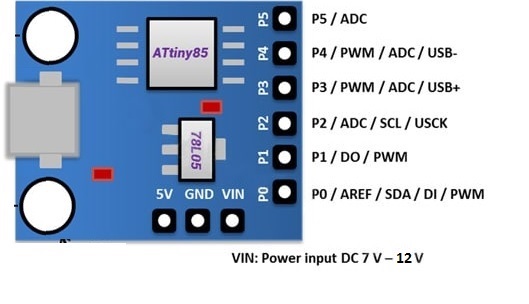
| Interface | Pin |
|---|---|
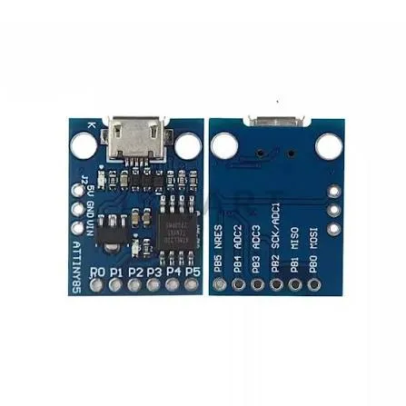
| Digital I/O | P0, P1, P2, P3, P4, P5 |
| PWM | P0, P1, P4, P5 (subject to board and peripheral configuration) |
| Analog Input | P2, P3, P4, P5 (ADC channels) |
| I2C | SDA: P0, SCL: P2 (software I2C or compatible library) |
| SPI | MOSI: P0, MISO: P1, SCK: P2 |
| Power | 5V, VIN, GND |
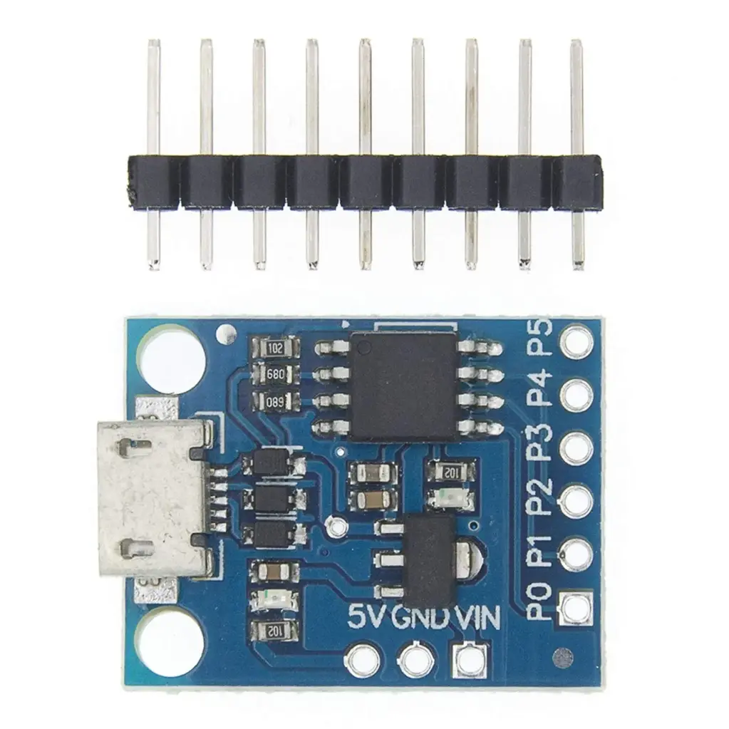
- Digital I/O: The ATtiny85 provides six GPIO pins. Their availability depends on the selected functions and the board's USB implementation. Use pinMode(), digitalRead(), and digitalWrite() to configure and control digital pins.
- Analog Inputs: The ATtiny85 has a 10-bit ADC. The available analog channels are associated with P2, P3, P4, and P5. Check the board pinout and USB configuration before assigning these pins to analog sensors.
- GND: Ground connection for the power supply and external modules.
- 5V: Regulated 5V supply rail. It can be used to power compatible external circuits within the regulator's current limits.
- VIN: External DC power input routed through the onboard voltage regulator. Use the recommended input range for the board.
- USB Connection: USB communication is implemented in software using V-USB. The USB data connections share microcontroller pins, so those pins are not freely available for other applications while USB functionality is required.
- Onboard LED: The user LED is connected to digital pin P1 on the common Digispark design. It can be controlled using digitalWrite(1, HIGH) and digitalWrite(1, LOW).
- Power LED: Indicates that the board is receiving power.
Wiring and Connection
The Digispark can be powered through its USB connector or through the VIN and GND pins using a suitable external DC supply.
- USB power: Connect the board to a computer or USB power source using its USB connector.
- External power: Connect the positive DC supply to VIN and the negative supply to GND. Use a supply within the board's recommended input range.
- Digital sensor: Connect the sensor output to an available GPIO pin and connect the sensor ground to GND.
- Analog sensor: Connect the sensor output to an available ADC pin and ensure that its output voltage does not exceed the microcontroller's permitted input voltage.
- I2C devices: Connect SDA to P0 and SCL to P2 when using a compatible I2C implementation.
Important: The USB data pins and other peripheral functions share GPIO resources. Check the pin assignments before connecting multiple devices. Do not connect motors, high-current loads, or relay coils directly to the GPIO pins; use suitable driver circuits.
Applications
- Small embedded control systems.
- LED controllers and lighting projects.
- Simple sensor monitoring and data acquisition.
- USB input devices and HID projects using compatible firmware.
- Low-power electronic control applications.
- Solar and battery-powered monitoring projects.
- Compact automation and switching systems.
- Small robotics and interactive projects.
- Prototyping and educational electronics projects.
Getting Started with Arduino IDE
- Install Arduino IDE: Download the IDE from the official Arduino software page.
- Add Digistump board support: Open Arduino IDE Preferences and add the following URL to Additional Boards Manager URLs:
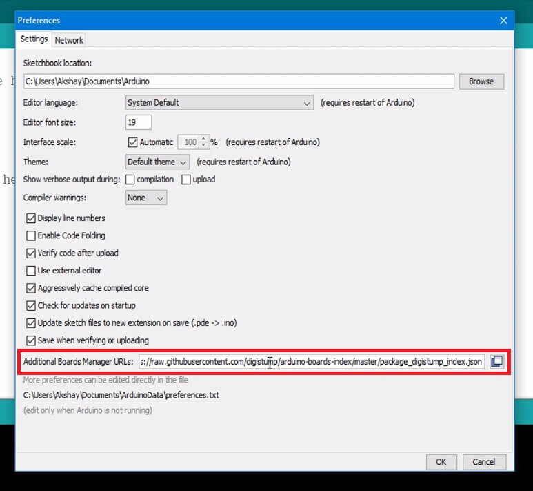
https://raw.githubusercontent.com/digistump/arduino-boards-index/master/package_digistump_index.json- Install the board package: Open Tools > Board > Boards Manager, search for Digistump AVR Boards, and install the package if it is available in your IDE configuration.
- Install the USB driver: On Windows, install the appropriate Digispark driver if required. The driver package is available from the DigistumpArduino releases page.
- Select the board: Choose Tools > Board > Digispark (Default - 16.5 MHz).
- Upload a sketch: Click Upload before connecting the Digispark. When the IDE prompts you to connect the device, plug it into the USB port. If it is already connected, disconnect and reconnect it.
The Digispark upload process differs from conventional Arduino boards. It generally does not require selecting a serial port in the Arduino IDE. After uploading, the sketch starts running. The bootloader normally waits briefly after power-up for a programming request before starting the application.
Code
This example flashes the onboard LED connected to P1.
const int LED_PIN = 1;

void setup() {
  pinMode(LED_PIN, OUTPUT);
}

void loop() {
  digitalWrite(LED_PIN, HIGH);
  delay(500);

  digitalWrite(LED_PIN, LOW);
  delay(500);
}Specifications
- Product: Digispark 85 Blue
- Microcontroller: ATtiny85
- Architecture: 8-bit AVR
- Clock Speed: 16.5 MHz (standard Digispark configuration)
- Operating Voltage: 5V
- Recommended External Input: 7–12V DC, subject to the onboard regulator's specifications
- Flash Memory: 8 KB
- SRAM: 512 bytes
- EEPROM: 512 bytes
- Digital I/O Pins: 6
- Analog Inputs: Up to 4 ADC channels
- PWM: Up to 4 outputs, depending on pin configuration
- ADC Resolution: 10-bit
- USB Interface: Software USB using V-USB and bootloader
- Communication: SPI and I2C-compatible interfaces
- Board Dimensions: Approximately 23 x 17.5 mm
Resources
- Arduino IDE Download
- Digistump Arduino Core and Board Support
- Digistump Drivers and Releases
- V-USB Software USB Library
- Arduino Language Reference
Digispark vs. Arduino Uno
| Specification | Digispark 85 Blue | Arduino Uno R3 |
|---|---|---|
| Microcontroller | ATtiny85 | ATmega328P |
| Architecture | 8-bit AVR | 8-bit AVR |
| Clock Speed | 16.5 MHz | 16 MHz |
| Operating Voltage | 5V | 5V |
| Flash Memory | 8 KB | 32 KB |
| SRAM | 512 bytes | 2 KB |
| EEPROM | 512 bytes | 1 KB |
| Digital I/O | 6 | 14 |
| Analog Inputs | 4 | 6 |
| USB Interface | Software USB (V-USB) | Dedicated USB-to-serial interface |
| Board Size | Approximately 23 x 17.5 mm | Approximately 68.6 x 53.4 mm |
The Digispark is intended for compact projects that require a small number of I/O connections and limited program memory. Its software-based USB implementation provides a way to program the board without a dedicated USB-to-serial converter, but it uses microcontroller resources and has limitations compared with the USB interface on an Arduino Uno. The Uno is more suitable for larger programs, projects requiring more I/O pins, and general-purpose development.
Features
- ATtiny85 8-bit AVR microcontroller.
- Compact board dimensions of approximately 23 x 17.5 mm.
- 16.5 MHz operating clock in the standard Digispark configuration.
- 6 digital I/O pins, with some pins shared with USB and other peripheral functions.
- 4 analog input channels, depending on pin configuration.
- 4 PWM-capable outputs, subject to pin-function limitations.
- Software-based USB communication using V-USB.
- Pre-installed bootloader for programming through the USB connection.
- SPI and I2C communication support through the ATtiny85 hardware interfaces and software libraries.
- Onboard power indicator and user LED.
- Onboard 5V voltage regulation for external VIN power.
- Arduino IDE compatibility through Digistump AVR board support.
Principle of Operation
The ATtiny85 executes the program stored in its Flash memory. The microcontroller reads input signals from connected sensors or switches, processes the program instructions, and controls outputs such as LEDs, relays, and other compatible electronic devices.
The Digispark uses the V-USB software library to emulate USB communication through GPIO pins. Its bootloader allows compatible sketches to be uploaded from the Arduino IDE without a separate hardware USB-to-serial converter.
The USB interface uses microcontroller resources that would otherwise be available for general-purpose I/O. Therefore, the USB-related pins should be considered when planning connections to external components.
Pinout
| Interface | Pin |
|---|---|
| Digital I/O | P0, P1, P2, P3, P4, P5 |
| PWM | P0, P1, P4, P5 (subject to board and peripheral configuration) |
| Analog Input | P2, P3, P4, P5 (ADC channels) |
| I2C | SDA: P0, SCL: P2 (software I2C or compatible library) |
| SPI | MOSI: P0, MISO: P1, SCK: P2 |
| Power | 5V, VIN, GND |
- Digital I/O: The ATtiny85 provides six GPIO pins. Their availability depends on the selected functions and the board's USB implementation. Use pinMode(), digitalRead(), and digitalWrite() to configure and control digital pins.
- Analog Inputs: The ATtiny85 has a 10-bit ADC. The available analog channels are associated with P2, P3, P4, and P5. Check the board pinout and USB configuration before assigning these pins to analog sensors.
- GND: Ground connection for the power supply and external modules.
- 5V: Regulated 5V supply rail. It can be used to power compatible external circuits within the regulator's current limits.
- VIN: External DC power input routed through the onboard voltage regulator. Use the recommended input range for the board.
- USB Connection: USB communication is implemented in software using V-USB. The USB data connections share microcontroller pins, so those pins are not freely available for other applications while USB functionality is required.
- Onboard LED: The user LED is connected to digital pin P1 on the common Digispark design. It can be controlled using digitalWrite(1, HIGH) and digitalWrite(1, LOW).
- Power LED: Indicates that the board is receiving power.
Wiring and Connection
The Digispark can be powered through its USB connector or through the VIN and GND pins using a suitable external DC supply.
- USB power: Connect the board to a computer or USB power source using its USB connector.
- External power: Connect the positive DC supply to VIN and the negative supply to GND. Use a supply within the board's recommended input range.
- Digital sensor: Connect the sensor output to an available GPIO pin and connect the sensor ground to GND.
- Analog sensor: Connect the sensor output to an available ADC pin and ensure that its output voltage does not exceed the microcontroller's permitted input voltage.
- I2C devices: Connect SDA to P0 and SCL to P2 when using a compatible I2C implementation.
Important: The USB data pins and other peripheral functions share GPIO resources. Check the pin assignments before connecting multiple devices. Do not connect motors, high-current loads, or relay coils directly to the GPIO pins; use suitable driver circuits.
Applications
- Small embedded control systems.
- LED controllers and lighting projects.
- Simple sensor monitoring and data acquisition.
- USB input devices and HID projects using compatible firmware.
- Low-power electronic control applications.
- Solar and battery-powered monitoring projects.
- Compact automation and switching systems.
- Small robotics and interactive projects.
- Prototyping and educational electronics projects.
Getting Started with Arduino IDE
- Install Arduino IDE: Download the IDE from the official Arduino software page.
- Add Digistump board support: Open Arduino IDE Preferences and add the following URL to Additional Boards Manager URLs:
https://raw.githubusercontent.com/digistump/arduino-boards-index/master/package_digistump_index.json- Install the board package: Open Tools > Board > Boards Manager, search for Digistump AVR Boards, and install the package if it is available in your IDE configuration.
- Install the USB driver: On Windows, install the appropriate Digispark driver if required. The driver package is available from the DigistumpArduino releases page.
- Select the board: Choose Tools > Board > Digispark (Default - 16.5 MHz).
- Upload a sketch: Click Upload before connecting the Digispark. When the IDE prompts you to connect the device, plug it into the USB port. If it is already connected, disconnect and reconnect it.
The Digispark upload process differs from conventional Arduino boards. It generally does not require selecting a serial port in the Arduino IDE. After uploading, the sketch starts running. The bootloader normally waits briefly after power-up for a programming request before starting the application.
Code
This example flashes the onboard LED connected to P1.
const int LED_PIN = 1;

void setup() {
  pinMode(LED_PIN, OUTPUT);
}

void loop() {
  digitalWrite(LED_PIN, HIGH);
  delay(500);

  digitalWrite(LED_PIN, LOW);
  delay(500);
}
Specifications
- Product: Digispark 85 Blue
- Microcontroller: ATtiny85
- Architecture: 8-bit AVR
- Clock Speed: 16.5 MHz (standard Digispark configuration)
- Operating Voltage: 5V
- Recommended External Input: 7–12V DC, subject to the onboard regulator's specifications
- Flash Memory: 8 KB
- SRAM: 512 bytes
- EEPROM: 512 bytes
- Digital I/O Pins: 6
- Analog Inputs: Up to 4 ADC channels
- PWM: Up to 4 outputs, depending on pin configuration
- ADC Resolution: 10-bit
- USB Interface: Software USB using V-USB and bootloader
- Communication: SPI and I2C-compatible interfaces
- Board Dimensions: Approximately 23 x 17.5 mm
Resources
- Arduino IDE Download
- Digistump Arduino Core and Board Support
- Digistump Drivers and Releases
- V-USB Software USB Library
- Arduino Language Reference
Digispark vs. Arduino Uno
| Specification | Digispark 85 Blue | Arduino Uno R3 |
|---|---|---|
| Microcontroller | ATtiny85 | ATmega328P |
| Architecture | 8-bit AVR | 8-bit AVR |
| Clock Speed | 16.5 MHz | 16 MHz |
| Operating Voltage | 5V | 5V |
| Flash Memory | 8 KB | 32 KB |
| SRAM | 512 bytes | 2 KB |
| EEPROM | 512 bytes | 1 KB |
| Digital I/O | 6 | 14 |
| Analog Inputs | 4 | 6 |
| USB Interface | Software USB (V-USB) | Dedicated USB-to-serial interface |
| Board Size | Approximately 23 x 17.5 mm | Approximately 68.6 x 53.4 mm |
The Digispark is intended for compact projects that require a small number of I/O connections and limited program memory. Its software-based USB implementation provides a way to program the board without a dedicated USB-to-serial converter, but it uses microcontroller resources and has limitations compared with the USB interface on an Arduino Uno. The Uno is more suitable for larger programs, projects requiring more I/O pins, and general-purpose development.