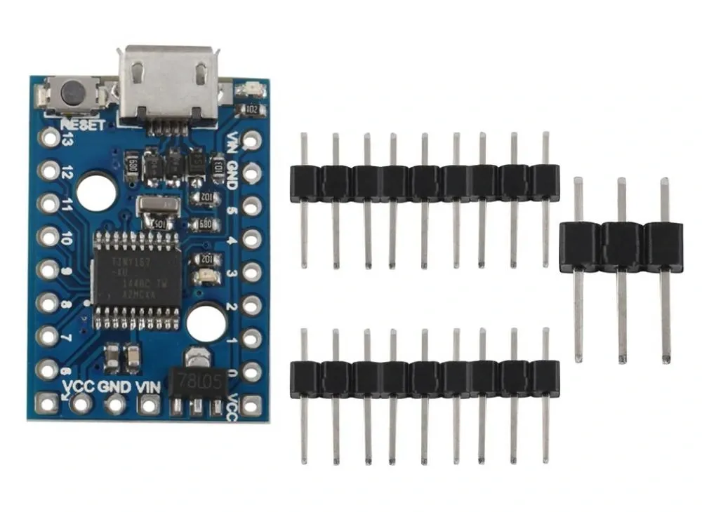
Features
- ATtiny167 microcontroller: 8-bit AVR processor operating at 16 MHz in the standard board configuration.
- Program memory: 16 KB Flash, with approximately 14.5 KB available after the bootloader allocation.
- USB connectivity: Micro USB connection for programming, USB device emulation, and USB-CDC virtual serial communication using the board's USB firmware.
- Digital I/O: Multiple GPIO connections for interfacing with sensors, switches, LEDs, and external circuits.
- Analog inputs: Up to 11 ADC channels are supported by the ATtiny167; the number exposed and available depends on the board pin configuration.
- Communication interfaces: UART, SPI, I2C/TWI, LIN, and USI peripheral support.
- PWM outputs: Hardware timer-based PWM for controlling LED brightness, motor drivers, and other suitable loads.
- Onboard button: Used for reset, programming, or user input, depending on the board configuration.
- Power options: Powered through USB or an external supply connected to VIN, with onboard voltage regulation.
- Status indicators: Power LED and onboard test/status LED.
- Compact construction: Small PCB with mounting holes and breadboard-friendly connections.
Principle of Operation
The ATtiny167 executes the application program stored in its internal Flash memory. It reads input signals from its GPIO and ADC channels, processes the data, and controls external components through digital outputs, PWM, and serial communication interfaces.
The Micro USB connector provides a connection to a computer for programming and USB communication. The board uses a bootloader and software USB implementation to support sketch uploading and USB device functions. This is not a dedicated hardware USB peripheral inside the ATtiny167, and USB communication uses specific microcontroller pins.
Once a program has been uploaded, the board can operate independently from the computer. Its UART, SPI, and I2C interfaces allow it to communicate with external microcontrollers, sensors, displays, and other peripheral devices.
Pinout

- Digital I/O: The board exposes GPIO connections for digital input and output. Their available functions depend on the selected board pin numbering and peripheral configuration.
- Analog inputs: ADC-capable pins can read analog signals from sensors and other low-voltage sources.
- PWM: Timer output pins can generate PWM signals for LED dimming and control applications.
- UART RX/TX: The board provides hardware serial communication on the pins identified as RX and TX in the pinout.
- SDA/SCL: I2C communication signals for connecting compatible peripherals.
- MOSI/MISO/SCK: SPI communication signals for high-speed synchronous data transfer.
- USB D+ and D−: USB data connections used by the board's USB implementation. These pins are shared with microcontroller I/O functions and should not be treated as freely available GPIO while USB is in use.
- 5V: Regulated 5V supply rail.
- VIN: External power input for the onboard regulator. Follow the board's specified input range.
- GND: Ground connection.
- RESET: Microcontroller reset connection.
Note: The ATtiny167 provides 16 general-purpose I/O lines at the microcontroller level. The number of usable pins on the development board is lower because some pins are assigned to USB, the crystal, reset, and other board functions. Refer to the supplied pinout when assigning GPIO numbers in your sketch.
Applications
- Compact embedded control systems.
- USB HID projects, including keyboard and mouse emulation where supported by the firmware.
- USB-CDC communication and serial debugging.
- Sensor monitoring and analog data acquisition.
- Small automation and control systems.
- LED and PWM-based control projects.
- UART, SPI, and I2C peripheral interfacing.
- Robotics and small electronic prototypes.
- Educational projects involving AVR microcontrollers and embedded programming.
Arduino IDE Setup
- Install the Arduino IDE from the official Arduino website.
- Open File > Preferences.
- Add the Digistump board package URL to Additional Boards Manager URLs:
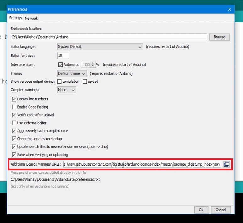
https://raw.githubusercontent.com/digistump/arduino-boards-index/master/package_digistump_index.json - Open Tools > Board > Boards Manager.
- Search for Digistump AVR Boards and install the package.
- Select Digispark Pro (16 MHz) if it is available in the installed board package.
- On Windows, install the Digistump USB drivers if required by the bootloader and operating system.
- Write or open a sketch and click Upload.
- Follow the upload prompt and connect or reconnect the board when requested.
The Digispark Pro uses a bootloader-based upload procedure. The board may need to be connected when the IDE requests it rather than remaining connected throughout the entire upload process. Board package versions and operating-system driver requirements can affect the exact procedure.
Code
This example blinks the onboard status LED, commonly connected to digital pin 1 on the Digispark Pro pin mapping. Confirm the LED pin against the supplied board pinout and installed board package.
const int LED_PIN = 1;

void setup() {
  pinMode(LED_PIN, OUTPUT);
}

void loop() {
  digitalWrite(LED_PIN, HIGH);
  delay(200);

  digitalWrite(LED_PIN, LOW);
  delay(200);
}The setup() function configures the LED pin as an output. The loop() function repeatedly switches the output HIGH and LOW, creating a blinking pattern with a 200 ms interval.
Specifications
- Microcontroller: ATtiny167
- Architecture: 8-bit AVR
- Clock frequency: 16 MHz
- Flash memory: 16 KB
- Flash available for application: Approximately 14.5 KB after bootloader allocation
- SRAM: 512 bytes
- EEPROM: 512 bytes
- Microcontroller I/O lines: 16 programmable I/O lines before board-level pin assignments
- ADC: 11-channel, 10-bit ADC on the microcontroller
- PWM: Hardware timer-based PWM; board documentation specifies 3 PWM channels
- Communication: UART, SPI, I2C/TWI, LIN, and USI
- USB connection: Micro USB with software-based USB support
- Operating voltage: 5V board configuration
- Voltage regulator: 5V regulator, specified by the board listing as 150mA
- External input: Board listing specifies 6–16V through the external power input; confirm the revision's VIN limits before use
- Dimensions: 26.7 x 18.3 x 4 mm
- Weight: Approximately 4 g
Electrical note: The 40mA figure sometimes listed as the maximum current per I/O pin is an absolute-limit specification, not a recommended continuous operating current. Keep GPIO current within the ATtiny167 datasheet's recommended operating limits. The board's 150mA regulator rating is also a regulator limit, not a guaranteed available current for every operating condition.
Resources
- Arduino IDE Download
- Arduino Language Reference
- Digistump Arduino Core
- Digistump Drivers and Releases
- ATtiny87/167 Official Datasheet
- PlatformIO Digispark Pro Board Reference
Comparison with Digispark ATtiny85

- Microcontroller: The Digispark Pro uses the ATtiny167, while the standard Digispark uses the ATtiny85.
- Flash memory: The ATtiny167 provides 16 KB compared with 8 KB on the ATtiny85.
- SRAM: The ATtiny167 provides 512 bytes, the same capacity as the ATtiny85.
- Connectivity: The Digispark Pro offers additional peripheral options, including a hardware UART, SPI, and I2C/USI support.
- I/O: The ATtiny167 board provides more exposed I/O connections than the standard ATtiny85 Digispark.
- USB: Both board families use software-based USB implementations rather than a dedicated USB peripheral inside the microcontroller.
The Digispark Pro is better suited to compact projects requiring additional memory, more I/O connections, and hardware serial communication. The ATtiny85 Digispark remains suitable for simpler applications where a smaller number of pins and lower memory capacity are sufficient.
Features
- ATtiny167 microcontroller: 8-bit AVR processor operating at 16 MHz in the standard board configuration.
- Program memory: 16 KB Flash, with approximately 14.5 KB available after the bootloader allocation.
- USB connectivity: Micro USB connection for programming, USB device emulation, and USB-CDC virtual serial communication using the board's USB firmware.
- Digital I/O: Multiple GPIO connections for interfacing with sensors, switches, LEDs, and external circuits.
- Analog inputs: Up to 11 ADC channels are supported by the ATtiny167; the number exposed and available depends on the board pin configuration.
- Communication interfaces: UART, SPI, I2C/TWI, LIN, and USI peripheral support.
- PWM outputs: Hardware timer-based PWM for controlling LED brightness, motor drivers, and other suitable loads.
- Onboard button: Used for reset, programming, or user input, depending on the board configuration.
- Power options: Powered through USB or an external supply connected to VIN, with onboard voltage regulation.
- Status indicators: Power LED and onboard test/status LED.
- Compact construction: Small PCB with mounting holes and breadboard-friendly connections.
Principle of Operation
The ATtiny167 executes the application program stored in its internal Flash memory. It reads input signals from its GPIO and ADC channels, processes the data, and controls external components through digital outputs, PWM, and serial communication interfaces.
The Micro USB connector provides a connection to a computer for programming and USB communication. The board uses a bootloader and software USB implementation to support sketch uploading and USB device functions. This is not a dedicated hardware USB peripheral inside the ATtiny167, and USB communication uses specific microcontroller pins.
Once a program has been uploaded, the board can operate independently from the computer. Its UART, SPI, and I2C interfaces allow it to communicate with external microcontrollers, sensors, displays, and other peripheral devices.
Pinout
- Digital I/O: The board exposes GPIO connections for digital input and output. Their available functions depend on the selected board pin numbering and peripheral configuration.
- Analog inputs: ADC-capable pins can read analog signals from sensors and other low-voltage sources.
- PWM: Timer output pins can generate PWM signals for LED dimming and control applications.
- UART RX/TX: The board provides hardware serial communication on the pins identified as RX and TX in the pinout.
- SDA/SCL: I2C communication signals for connecting compatible peripherals.
- MOSI/MISO/SCK: SPI communication signals for high-speed synchronous data transfer.
- USB D+ and D−: USB data connections used by the board's USB implementation. These pins are shared with microcontroller I/O functions and should not be treated as freely available GPIO while USB is in use.
- 5V: Regulated 5V supply rail.
- VIN: External power input for the onboard regulator. Follow the board's specified input range.
- GND: Ground connection.
- RESET: Microcontroller reset connection.
Note: The ATtiny167 provides 16 general-purpose I/O lines at the microcontroller level. The number of usable pins on the development board is lower because some pins are assigned to USB, the crystal, reset, and other board functions. Refer to the supplied pinout when assigning GPIO numbers in your sketch.
Applications
- Compact embedded control systems.
- USB HID projects, including keyboard and mouse emulation where supported by the firmware.
- USB-CDC communication and serial debugging.
- Sensor monitoring and analog data acquisition.
- Small automation and control systems.
- LED and PWM-based control projects.
- UART, SPI, and I2C peripheral interfacing.
- Robotics and small electronic prototypes.
- Educational projects involving AVR microcontrollers and embedded programming.
Arduino IDE Setup
- Install the Arduino IDE from the official Arduino website.
- Open File > Preferences.
- Add the Digistump board package URL to Additional Boards Manager URLs:
https://raw.githubusercontent.com/digistump/arduino-boards-index/master/package_digistump_index.json - Open Tools > Board > Boards Manager.
- Search for Digistump AVR Boards and install the package.
- Select Digispark Pro (16 MHz) if it is available in the installed board package.
- On Windows, install the Digistump USB drivers if required by the bootloader and operating system.
- Write or open a sketch and click Upload.
- Follow the upload prompt and connect or reconnect the board when requested.
The Digispark Pro uses a bootloader-based upload procedure. The board may need to be connected when the IDE requests it rather than remaining connected throughout the entire upload process. Board package versions and operating-system driver requirements can affect the exact procedure.
Code
This example blinks the onboard status LED, commonly connected to digital pin 1 on the Digispark Pro pin mapping. Confirm the LED pin against the supplied board pinout and installed board package.
const int LED_PIN = 1;

void setup() {
  pinMode(LED_PIN, OUTPUT);
}

void loop() {
  digitalWrite(LED_PIN, HIGH);
  delay(200);

  digitalWrite(LED_PIN, LOW);
  delay(200);
}
The setup() function configures the LED pin as an output. The loop() function repeatedly switches the output HIGH and LOW, creating a blinking pattern with a 200 ms interval.
Specifications
- Microcontroller: ATtiny167
- Architecture: 8-bit AVR
- Clock frequency: 16 MHz
- Flash memory: 16 KB
- Flash available for application: Approximately 14.5 KB after bootloader allocation
- SRAM: 512 bytes
- EEPROM: 512 bytes
- Microcontroller I/O lines: 16 programmable I/O lines before board-level pin assignments
- ADC: 11-channel, 10-bit ADC on the microcontroller
- PWM: Hardware timer-based PWM; board documentation specifies 3 PWM channels
- Communication: UART, SPI, I2C/TWI, LIN, and USI
- USB connection: Micro USB with software-based USB support
- Operating voltage: 5V board configuration
- Voltage regulator: 5V regulator, specified by the board listing as 150mA
- External input: Board listing specifies 6–16V through the external power input; confirm the revision's VIN limits before use
- Dimensions: 26.7 x 18.3 x 4 mm
- Weight: Approximately 4 g
Electrical note: The 40mA figure sometimes listed as the maximum current per I/O pin is an absolute-limit specification, not a recommended continuous operating current. Keep GPIO current within the ATtiny167 datasheet's recommended operating limits. The board's 150mA regulator rating is also a regulator limit, not a guaranteed available current for every operating condition.
Resources
- Arduino IDE Download
- Arduino Language Reference
- Digistump Arduino Core
- Digistump Drivers and Releases
- ATtiny87/167 Official Datasheet
- PlatformIO Digispark Pro Board Reference
Comparison with Digispark ATtiny85
- Microcontroller: The Digispark Pro uses the ATtiny167, while the standard Digispark uses the ATtiny85.
- Flash memory: The ATtiny167 provides 16 KB compared with 8 KB on the ATtiny85.
- SRAM: The ATtiny167 provides 512 bytes, the same capacity as the ATtiny85.
- Connectivity: The Digispark Pro offers additional peripheral options, including a hardware UART, SPI, and I2C/USI support.
- I/O: The ATtiny167 board provides more exposed I/O connections than the standard ATtiny85 Digispark.
- USB: Both board families use software-based USB implementations rather than a dedicated USB peripheral inside the microcontroller.
The Digispark Pro is better suited to compact projects requiring additional memory, more I/O connections, and hardware serial communication. The ATtiny85 Digispark remains suitable for simpler applications where a smaller number of pins and lower memory capacity are sufficient.