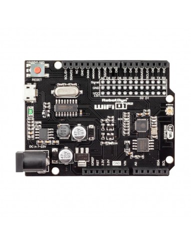
The board integrates an ESP8266 microcontroller with onboard flash memory, a CH340C USB-to-serial converter, and both a built-in PCB antenna and an external antenna connector. Programming is performed using the Arduino IDE, just like traditional Arduino boards.
Features
- ESP8266 Wi-Fi microcontroller.
- Arduino UNO-compatible layout.
- Built-in Wi-Fi antenna.
- External antenna connector.
- CH340C USB-to-serial interface.
- Supports Arduino IDE programming.
- OTA (Over-The-Air) firmware updates.
- Compact and lightweight design.
Specifications
- Microcontroller: ESP8266
- USB-TTL Converter: CH340C
- Clock Frequency: Up to 160 MHz
- Operating Voltage: 3.3V
- Flash Memory: 32Mb (4MB)
- Wi-Fi: 802.11 b/g/n (2.4 GHz)
- Logic Level: 3.3V (5V tolerant inputs on some pins)
- Digital I/O: 11
- Analogue Input: 1 (A0)
- Power Input (USB): 5V
- Power Input (VIN / DC Jack): 9–24V
- Power Output: 3.3V / 5V
- Interface: Serial / OTA
- Dimensions: 53.34 × 68.51 mm
- Weight: 8 g
- Operating Temperature: −40°C to +125°C
- Antenna: Built-in / External
USB Driver Requirement
The board uses a CH340 USB converter. Install the CH340 driver if your computer does not detect the board.
Programming Environment
Compatible with the Arduino IDE. Install ESP8266 board support via:
- Arduino IDE → Preferences → Additional Boards Manager URLs
- Add ESP8266 board package URL:
http://arduino.esp8266.com/stable/package_esp8266com_index.json - Tools → Board → Boards Manager → ESP8266
Required Libraries
OTA updates require the ArduinoOTA library (included with ESP8266 package).
#include <ESP8266WiFi.h>
#include <WiFiUdp.h>
#include <ArduinoOTA.h>
Basic Blink Example
void setup() {
  pinMode(LED_BUILTIN, OUTPUT);
}

void loop() {
  digitalWrite(LED_BUILTIN, LOW);
  delay(500);
  digitalWrite(LED_BUILTIN, HIGH);
  delay(500);
}
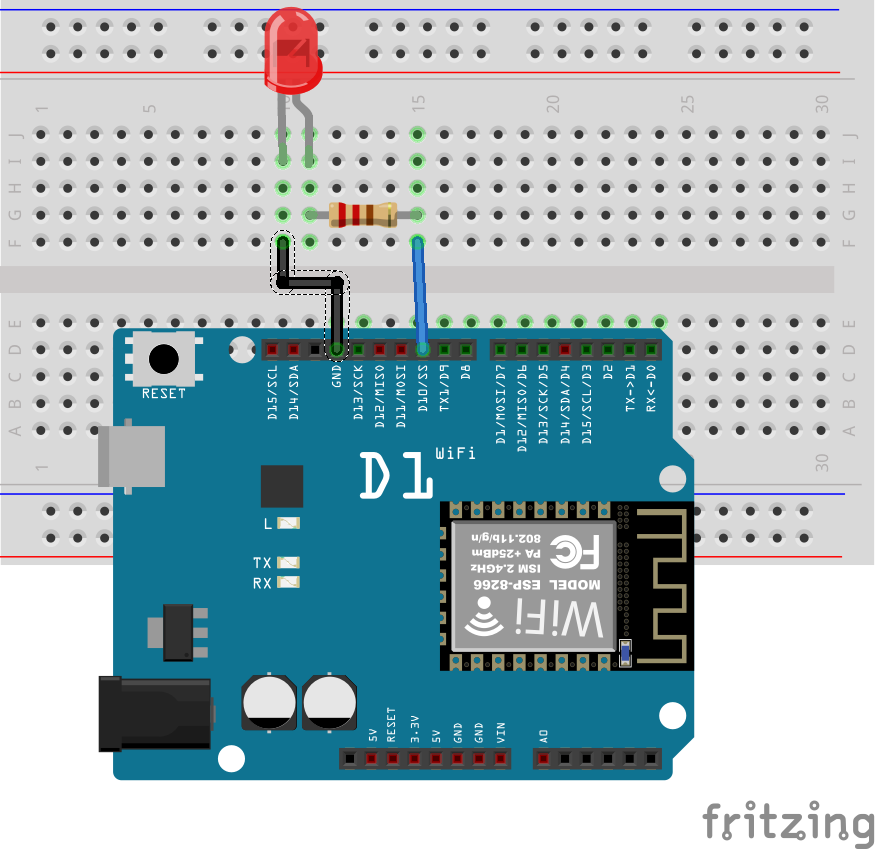
Hardware Example
Connect components as shown in the schematic to test a basic LED blink project.
OTA Update Preparation
OTA (Over-The-Air) updates allow wireless firmware uploads without USB cables. Modern Arduino IDE versions already include required tools — Python manual installation is typically unnecessary.
Basic OTA Example
#include <ESP8266WiFi.h>
#include <WiFiUdp.h>
#include <ArduinoOTA.h>

const char* ssid = "YOUR_SSID";
const char* password = "YOUR_PASSWORD";

void setup() {
  pinMode(LED_BUILTIN, OUTPUT);

  Serial.begin(115200);

  WiFi.mode(WIFI_STA);
  WiFi.begin(ssid, password);

  while (WiFi.waitForConnectResult() != WL_CONNECTED) {
    delay(5000);
    ESP.restart();
  }

  ArduinoOTA.begin();
}

void loop() {
  ArduinoOTA.handle();

  digitalWrite(LED_BUILTIN, LOW);
  delay(500);
  digitalWrite(LED_BUILTIN, HIGH);
  delay(500);
}
How OTA Works
- Upload OTA-enabled sketch via USB once.
- Board connects to Wi-Fi network.
- New network port appears in Arduino IDE.
- Future uploads can be done wirelessly.
Important OTA Note
OTA functionality must be included in every sketch you upload via OTA. Otherwise, the wireless update capability will be lost.
Applications
- IoT devices
- Wireless sensors
- Smart home systems
- Remote monitoring
- Network-connected controllers
Tips & Information
- ESP8266 operates at 3.3V logic level.
- Avoid applying 5V directly to GPIO pins.
- Use level shifters for 5V peripherals if needed.
- External antenna improves Wi-Fi range.
- VIN input supports wide voltage range.
- OTA is ideal for hard-to-reach installations.
The board integrates an ESP8266 microcontroller with onboard flash memory, a CH340C USB-to-serial converter, and both a built-in PCB antenna and an external antenna connector. Programming is performed using the Arduino IDE, just like traditional Arduino boards.
Features
- ESP8266 Wi-Fi microcontroller.
- Arduino UNO-compatible layout.
- Built-in Wi-Fi antenna.
- External antenna connector.
- CH340C USB-to-serial interface.
- Supports Arduino IDE programming.
- OTA (Over-The-Air) firmware updates.
- Compact and lightweight design.
Specifications
- Microcontroller: ESP8266
- USB-TTL Converter: CH340C
- Clock Frequency: Up to 160 MHz
- Operating Voltage: 3.3V
- Flash Memory: 32Mb (4MB)
- Wi-Fi: 802.11 b/g/n (2.4 GHz)
- Logic Level: 3.3V (5V tolerant inputs on some pins)
- Digital I/O: 11
- Analogue Input: 1 (A0)
- Power Input (USB): 5V
- Power Input (VIN / DC Jack): 9–24V
- Power Output: 3.3V / 5V
- Interface: Serial / OTA
- Dimensions: 53.34 × 68.51 mm
- Weight: 8 g
- Operating Temperature: −40°C to +125°C
- Antenna: Built-in / External
USB Driver Requirement
The board uses a CH340 USB converter. Install the CH340 driver if your computer does not detect the board.
Programming Environment
Compatible with the Arduino IDE. Install ESP8266 board support via:
- Arduino IDE → Preferences → Additional Boards Manager URLs
- Add ESP8266 board package URL:
http://arduino.esp8266.com/stable/package_esp8266com_index.json - Tools → Board → Boards Manager → ESP8266
Required Libraries
OTA updates require the ArduinoOTA library (included with ESP8266 package).
#include <ESP8266WiFi.h>
#include <WiFiUdp.h>
#include <ArduinoOTA.h>
Basic Blink Example
void setup() {
  pinMode(LED_BUILTIN, OUTPUT);
}

void loop() {
  digitalWrite(LED_BUILTIN, LOW);
  delay(500);
  digitalWrite(LED_BUILTIN, HIGH);
  delay(500);
}
Hardware Example
Connect components as shown in the schematic to test a basic LED blink project.
OTA Update Preparation
OTA (Over-The-Air) updates allow wireless firmware uploads without USB cables. Modern Arduino IDE versions already include required tools — Python manual installation is typically unnecessary.
Basic OTA Example
#include <ESP8266WiFi.h>
#include <WiFiUdp.h>
#include <ArduinoOTA.h>

const char* ssid = "YOUR_SSID";
const char* password = "YOUR_PASSWORD";

void setup() {
  pinMode(LED_BUILTIN, OUTPUT);

  Serial.begin(115200);

  WiFi.mode(WIFI_STA);
  WiFi.begin(ssid, password);

  while (WiFi.waitForConnectResult() != WL_CONNECTED) {
    delay(5000);
    ESP.restart();
  }

  ArduinoOTA.begin();
}

void loop() {
  ArduinoOTA.handle();

  digitalWrite(LED_BUILTIN, LOW);
  delay(500);
  digitalWrite(LED_BUILTIN, HIGH);
  delay(500);
}
How OTA Works
- Upload OTA-enabled sketch via USB once.
- Board connects to Wi-Fi network.
- New network port appears in Arduino IDE.
- Future uploads can be done wirelessly.
Important OTA Note
OTA functionality must be included in every sketch you upload via OTA. Otherwise, the wireless update capability will be lost.
Applications
- IoT devices
- Wireless sensors
- Smart home systems
- Remote monitoring
- Network-connected controllers
Tips & Information
- ESP8266 operates at 3.3V logic level.
- Avoid applying 5V directly to GPIO pins.
- Use level shifters for 5V peripherals if needed.
- External antenna improves Wi-Fi range.
- VIN input supports wide voltage range.
- OTA is ideal for hard-to-reach installations.