Features
- Low-power operation: 0.9 mA normal mode, 1.25 mA high-performance mode
- Smart FIFO buffer up to 8 bytes based on features
- Full-scale acceleration: ±2/±4/±8/±16 g
- Full-scale angular rate: ±125/±245/±500/±1000/±2000 DPS
- Analog supply voltage: 1.71–5V
- SPI/I²C serial interface with main processor synchronization
- Always-on low-power accelerometer and gyroscope modes
Specifications
- Power consumption: 0.9 mA (combo normal), 1.25 mA (high-performance)
- Acceleration full scale: ±2/±4/±8/±16 g
- Angular rate full scale: ±125/±245/±500/±1000/±2000 DPS
- Interface: SPI / I²C
- Supply voltage: 1.71–5V
- Smart FIFO buffer: up to 8 bytes
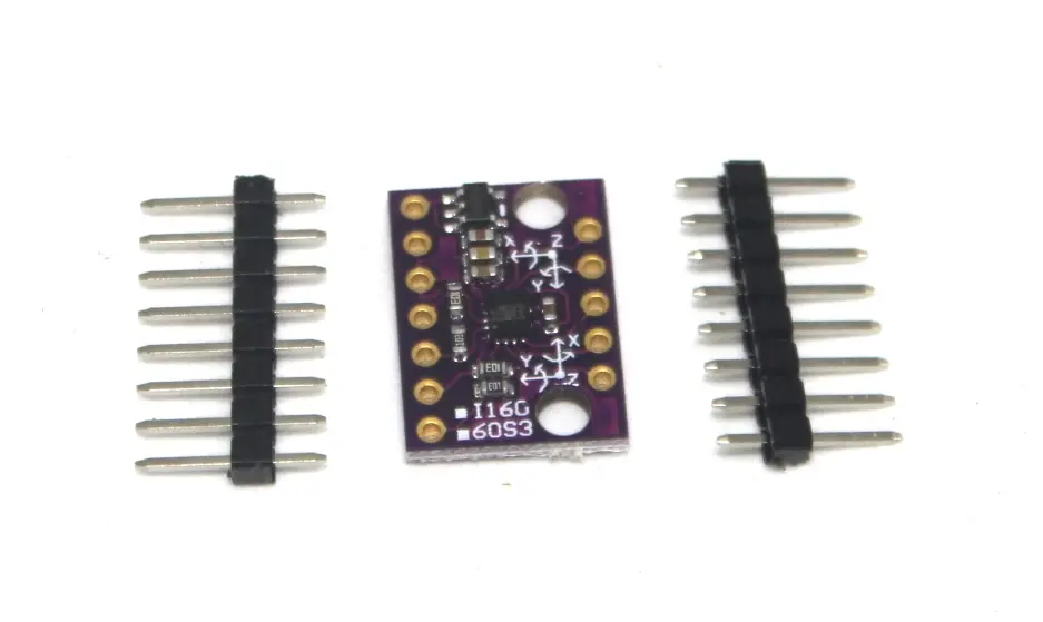
Pinout of the Module
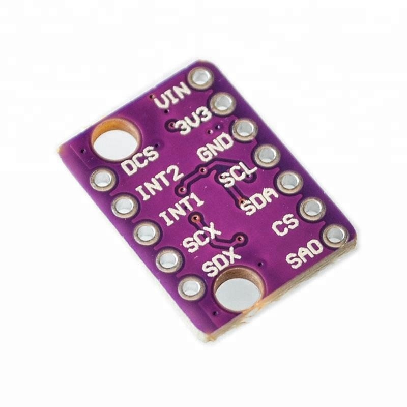
| Pin Label |
Pin Function |
Notes |
| GND |
Ground |
0V supply. Spare GND for connecting additional devices. |
| VDD |
Power Supply |
Regulated 1.8–3.6V. Spare VDD for general use. |
| SDA/SDI |
I²C: Serial Data / SPI: MOSI |
I²C bidirectional, SPI data input |
| SCL |
Serial Clock |
Clock for I²C and SPI |
| SDO/SA0 |
I²C: Address / SPI: MISO |
I²C address LSB, SPI data output |
| CS |
I²C: Mode / SPI: CS |
Select I²C (disconnected) or SPI chip select |
| INT2 |
Accel/Gyro Interrupt 2 |
Programmable interrupt output |
| INT1 |
Accel/Gyro Interrupt 1 |
Programmable interrupt output |
| OCS |
Aux SPI 3-wire |
For attaching slave I²C/3-wire devices (optional) |
| SCX |
Aux Clock |
Auxiliary interface |
| SDX |
Aux Data |
Auxiliary interface |
Arduino Example Code
#include "Arduino_LSM6DS3.h"

void setup() {
  Serial.begin(9600);
  while (!Serial); // Wait for serial initialization

  Serial.print("LSM6DS3 IMU initialization ");
  if (IMU.begin()) {
    Serial.println("completed successfully.");
  } else {
    Serial.println("FAILED.");
    IMU.end();
    while (1);
  }
  Serial.println();
}

void loop() {
  char buffer[8];
  float ax, ay, az; // accelerometer
  float gx, gy, gz; // gyroscope

  if (IMU.accelerationAvailable() && IMU.gyroscopeAvailable() &&
      IMU.readAcceleration(ax, ay, az) && IMU.readGyroscope(gx, gy, gz)) {

    Serial.print("ax = "); Serial.print(dtostrf(ax, 4, 1, buffer)); Serial.print(" g, ");
    Serial.print("ay = "); Serial.print(dtostrf(ay, 4, 1, buffer)); Serial.print(" g, ");
    Serial.print("az = "); Serial.print(dtostrf(az, 4, 1, buffer)); Serial.print(" g, ");

    Serial.print("gx = "); Serial.print(dtostrf(gx, 7, 1, buffer)); Serial.print(" °/s, ");
    Serial.print("gy = "); Serial.print(dtostrf(gy, 7, 1, buffer)); Serial.print(" °/s, ");
    Serial.print("gz = "); Serial.print(dtostrf(gz, 7, 1, buffer)); Serial.println(" °/s");
  }
  delay(1000);
}
Applications
- Robotics motion control
- IoT wearable devices
- Tilt sensing
- Tap and shock detection
- Consumer electronics with motion control
Resources
Features
- Low-power operation: 0.9 mA normal mode, 1.25 mA high-performance mode
- Smart FIFO buffer up to 8 bytes based on features
- Full-scale acceleration: ±2/±4/±8/±16 g
- Full-scale angular rate: ±125/±245/±500/±1000/±2000 DPS
- Analog supply voltage: 1.71–5V
- SPI/I²C serial interface with main processor synchronization
- Always-on low-power accelerometer and gyroscope modes
Specifications
- Power consumption: 0.9 mA (combo normal), 1.25 mA (high-performance)
- Acceleration full scale: ±2/±4/±8/±16 g
- Angular rate full scale: ±125/±245/±500/±1000/±2000 DPS
- Interface: SPI / I²C
- Supply voltage: 1.71–5V
- Smart FIFO buffer: up to 8 bytes
Pinout of the Module
| Pin Label |
Pin Function |
Notes |
| GND |
Ground |
0V supply. Spare GND for connecting additional devices. |
| VDD |
Power Supply |
Regulated 1.8–3.6V. Spare VDD for general use. |
| SDA/SDI |
I²C: Serial Data / SPI: MOSI |
I²C bidirectional, SPI data input |
| SCL |
Serial Clock |
Clock for I²C and SPI |
| SDO/SA0 |
I²C: Address / SPI: MISO |
I²C address LSB, SPI data output |
| CS |
I²C: Mode / SPI: CS |
Select I²C (disconnected) or SPI chip select |
| INT2 |
Accel/Gyro Interrupt 2 |
Programmable interrupt output |
| INT1 |
Accel/Gyro Interrupt 1 |
Programmable interrupt output |
| OCS |
Aux SPI 3-wire |
For attaching slave I²C/3-wire devices (optional) |
| SCX |
Aux Clock |
Auxiliary interface |
| SDX |
Aux Data |
Auxiliary interface |
Arduino Example Code
#include "Arduino_LSM6DS3.h"

void setup() {
  Serial.begin(9600);
  while (!Serial); // Wait for serial initialization

  Serial.print("LSM6DS3 IMU initialization ");
  if (IMU.begin()) {
    Serial.println("completed successfully.");
  } else {
    Serial.println("FAILED.");
    IMU.end();
    while (1);
  }
  Serial.println();
}

void loop() {
  char buffer[8];
  float ax, ay, az; // accelerometer
  float gx, gy, gz; // gyroscope

  if (IMU.accelerationAvailable() && IMU.gyroscopeAvailable() &&
      IMU.readAcceleration(ax, ay, az) && IMU.readGyroscope(gx, gy, gz)) {

    Serial.print("ax = "); Serial.print(dtostrf(ax, 4, 1, buffer)); Serial.print(" g, ");
    Serial.print("ay = "); Serial.print(dtostrf(ay, 4, 1, buffer)); Serial.print(" g, ");
    Serial.print("az = "); Serial.print(dtostrf(az, 4, 1, buffer)); Serial.print(" g, ");

    Serial.print("gx = "); Serial.print(dtostrf(gx, 7, 1, buffer)); Serial.print(" °/s, ");
    Serial.print("gy = "); Serial.print(dtostrf(gy, 7, 1, buffer)); Serial.print(" °/s, ");
    Serial.print("gz = "); Serial.print(dtostrf(gz, 7, 1, buffer)); Serial.println(" °/s");
  }
  delay(1000);
}
Applications
- Robotics motion control
- IoT wearable devices
- Tilt sensing
- Tap and shock detection
- Consumer electronics with motion control
Resources