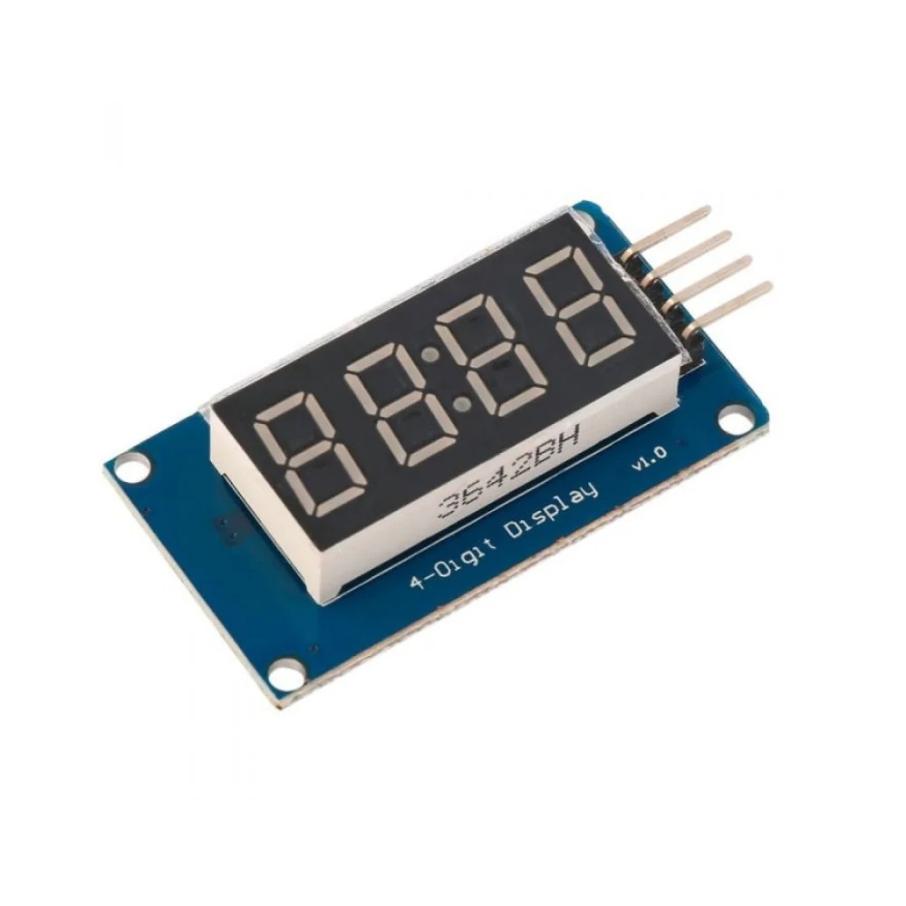
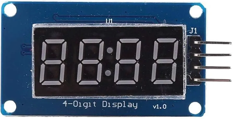
This display is widely used in applications requiring clear numerical output such as clocks, counters, timers, voltmeters, temperature monitors, and measurement systems. Thanks to its adjustable brightness and efficient communication protocol, it provides excellent readability while maintaining low power consumption.
Features
- TM1637 Driver IC: Simplified 2-wire digital communication (CLK, DIO).
- 4-Digit Display: Red common anode 7-segment LED display.
- Brightness Adjustment: Software-controlled brightness (8 levels).
- Low Power Consumption: Efficient LED driving architecture.
- Minimal Wiring: Only two signal pins required.
- Integrated Driver: No additional multiplexing required.
- Negative Number Support: Built-in segment control.
- Wide Compatibility: Works with 3.3V and 5V systems.
- Stable Operation: Internal timing and scanning control.
Specifications
- Driver IC: TM1637
- Display Type: 4-Digit 7-Segment LED (Red)
- Segment Configuration: Common Anode
- Operating Voltage: 3.3V – 5V DC
- Operating Current: 30 – 80 mA (typical)
- Communication Interface: 2-Wire Digital (CLK, DIO)
- Brightness Levels: 8 (0–7)
- Module Dimensions: Approx. 42 × 24 × 11 mm
Pinout

| Pin | Name | Description |
|---|---|---|
| 1 | CLK | Clock signal input |
| 2 | DIO | Data input/output |
| 3 | VCC | Power supply (3.3V – 5V) |
| 4 | GND | Ground |
Arduino Library
- Install the TM1637Display library:
https://github.com/avishorp/TM1637
Wiring with Arduino
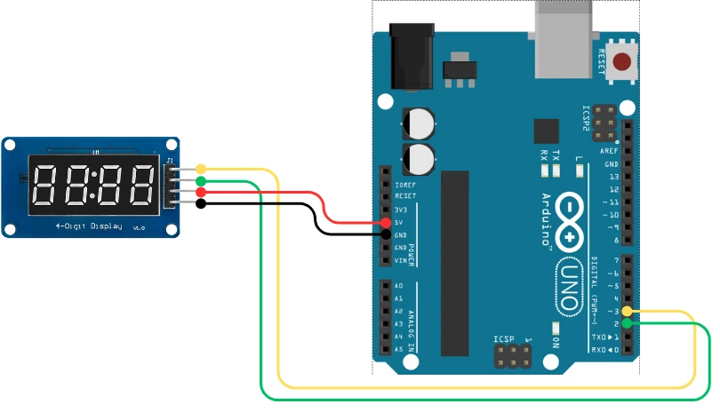
- CLK → Arduino Digital Pin 2
- DIO → Arduino Digital Pin 3
- VCC → 5V
- GND → GND
Example Arduino Code
#include "Arduino.h"
#include "TM1637Display.h"

#define CLK 2
#define DIO 3
#define TEST_DELAY 2000

const uint8_t SEG_DONE[] = {
  SEG_B | SEG_C | SEG_D | SEG_E | SEG_G,           // d
  SEG_A | SEG_B | SEG_C | SEG_D | SEG_E | SEG_F,   // O
  SEG_C | SEG_E | SEG_G,                           // n
  SEG_A | SEG_D | SEG_E | SEG_F | SEG_G            // E
};

TM1637Display display(CLK, DIO);

void setup() { }

void loop() {
  uint8_t data[] = { 0xff, 0xff, 0xff, 0xff };
  display.setBrightness(7);

  display.setSegments(data);
  delay(TEST_DELAY);

  display.showNumberDec(1234);
  delay(TEST_DELAY);

  display.showNumberDec(301, false);
  delay(TEST_DELAY);

  display.showNumberDec(-999);
  delay(TEST_DELAY);

  display.showNumberHexEx(0xf1af);
  delay(TEST_DELAY);

  display.setSegments(SEG_DONE);
  while(1);
}
Applications
- Digital clocks and timers.
- Counters and measurement displays.
- Temperature and sensor readouts.
- Embedded system dashboards.
- DIY electronics projects.
This display is widely used in applications requiring clear numerical output such as clocks, counters, timers, voltmeters, temperature monitors, and measurement systems. Thanks to its adjustable brightness and efficient communication protocol, it provides excellent readability while maintaining low power consumption.
Features
- TM1637 Driver IC: Simplified 2-wire digital communication (CLK, DIO).
- 4-Digit Display: Red common anode 7-segment LED display.
- Brightness Adjustment: Software-controlled brightness (8 levels).
- Low Power Consumption: Efficient LED driving architecture.
- Minimal Wiring: Only two signal pins required.
- Integrated Driver: No additional multiplexing required.
- Negative Number Support: Built-in segment control.
- Wide Compatibility: Works with 3.3V and 5V systems.
- Stable Operation: Internal timing and scanning control.
Specifications
- Driver IC: TM1637
- Display Type: 4-Digit 7-Segment LED (Red)
- Segment Configuration: Common Anode
- Operating Voltage: 3.3V – 5V DC
- Operating Current: 30 – 80 mA (typical)
- Communication Interface: 2-Wire Digital (CLK, DIO)
- Brightness Levels: 8 (0–7)
- Module Dimensions: Approx. 42 × 24 × 11 mm
Pinout
| Pin | Name | Description |
|---|---|---|
| 1 | CLK | Clock signal input |
| 2 | DIO | Data input/output |
| 3 | VCC | Power supply (3.3V – 5V) |
| 4 | GND | Ground |
Arduino Library
- Install the TM1637Display library:
https://github.com/avishorp/TM1637
Wiring with Arduino
- CLK → Arduino Digital Pin 2
- DIO → Arduino Digital Pin 3
- VCC → 5V
- GND → GND
Example Arduino Code
#include "Arduino.h"
#include "TM1637Display.h"

#define CLK 2
#define DIO 3
#define TEST_DELAY 2000

const uint8_t SEG_DONE[] = {
  SEG_B | SEG_C | SEG_D | SEG_E | SEG_G,           // d
  SEG_A | SEG_B | SEG_C | SEG_D | SEG_E | SEG_F,   // O
  SEG_C | SEG_E | SEG_G,                           // n
  SEG_A | SEG_D | SEG_E | SEG_F | SEG_G            // E
};

TM1637Display display(CLK, DIO);

void setup() { }

void loop() {
  uint8_t data[] = { 0xff, 0xff, 0xff, 0xff };
  display.setBrightness(7);

  display.setSegments(data);
  delay(TEST_DELAY);

  display.showNumberDec(1234);
  delay(TEST_DELAY);

  display.showNumberDec(301, false);
  delay(TEST_DELAY);

  display.showNumberDec(-999);
  delay(TEST_DELAY);

  display.showNumberHexEx(0xf1af);
  delay(TEST_DELAY);

  display.setSegments(SEG_DONE);
  while(1);
}
Applications
- Digital clocks and timers.
- Counters and measurement displays.
- Temperature and sensor readouts.
- Embedded system dashboards.
- DIY electronics projects.