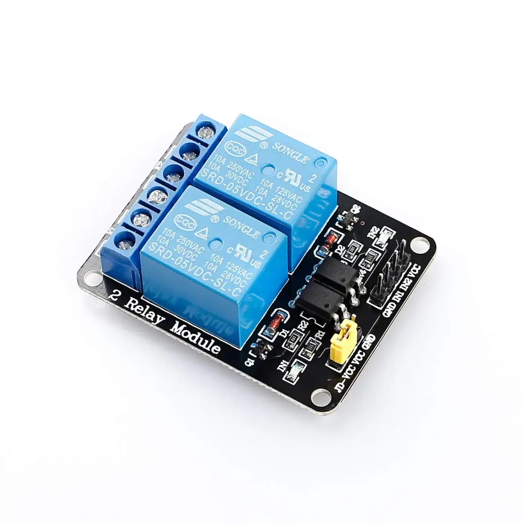
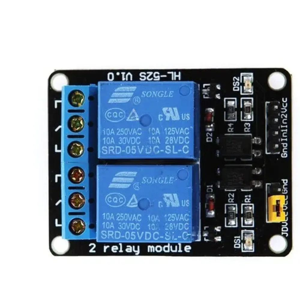
Features
- 2 Independent Relay Channels: Two separate relays can be controlled independently from the connected microcontroller.
- High-Level Trigger: Each relay is activated when its corresponding control input is driven HIGH.
- Optocoupler Isolation: Optocouplers are provided on the input side to electrically isolate the controller signal from the relay-driving section.
- High-Current Switching: Each relay provides contacts rated up to 10A at 250VAC or 10A at 30VDC, subject to the relay and load conditions.
- NO and NC Contacts: Each relay provides Normally Open (NO), Normally Closed (NC), and Common (COM) contacts, allowing either normally-off or normally-on load operation.
- LED Indicators: Onboard LEDs provide visual indication of the relay/control status.
- Power Indicator: A dedicated indicator shows when the module is powered.
- High-Impedance Control Input: The control interface is designed to require only a small input current from the connected controller.
- Flexible Power Configuration: The module includes a jumper arrangement that allows the relay/control power configuration to be selected according to the board design.
- Standard Interface: The control pins can be connected to common microcontrollers and control systems.
- Compact Design: Combines two relays, optocouplers, indicators, and control circuitry on a compact PCB.
Principle of Operation
A relay is an electrically controlled mechanical switch. Instead of connecting the microcontroller directly to the high-current load, the microcontroller provides a low-voltage control signal to the relay module. The relay then mechanically switches the electrical connection between its COM, NO, and NC contacts. This module uses a high-level trigger. When the input of a relay channel is driven HIGH, the corresponding relay driver is activated and the relay coil is energized. The relay contacts then change state: the COM contact moves from NC to NO. For example, when a load is connected between COM and NO, the load normally remains OFF while the relay is inactive. When the input signal becomes HIGH, the relay activates and connects COM to NO, turning the load ON.
Alternatively, a load can be connected between COM and NC. In this configuration, the load is normally powered while the relay is inactive. When the relay is activated, COM moves away from NC and the load is switched OFF. The onboard optocouplers transfer the control signal using light rather than a direct electrical connection between the controller-side input circuit and the relay-driving circuitry. This provides galvanic isolation between these sections and can help reduce the transfer of electrical noise and voltage disturbances from the relay/load side toward the controller.
The optocoupler should not, however, be interpreted as automatically making every connection on the module completely isolated. The actual isolation achieved depends on the module's power configuration, jumper arrangement, wiring, and the way the external power supplies are connected.
Pinout

| Pin / Terminal | Function |
|---|---|
| VCC | 5V supply for the module/control section according to the board configuration. |
| GND | Ground connection for the module/power supply. |
| SGND | Signal/control-side ground used according to the module's jumper and isolation configuration. |
| IN1 | High-level control input for Relay 1. |
| IN2 | High-level control input for Relay 2. |
| COM1 | Common contact of Relay 1. |
| NO1 | Normally Open contact of Relay 1. |
| NC1 | Normally Closed contact of Relay 1. |
| COM2 | Common contact of Relay 2. |
| NO2 | Normally Open contact of Relay 2. |
| NC2 | Normally Closed contact of Relay 2. |
Wiring

The control interface can be connected to digital output pins of a compatible microcontroller. The exact GPIO numbers depend on the development board being used.
| Relay Module | Arduino UNO Example | ESP32 Example |
|---|---|---|
| VCC | 5V | 5V/VIN or suitable external supply according to module requirements |
| GND / SGND | GND | GND |
| IN1 | D2 | GPIO18 |
| IN2 | D3 | GPIO19 |
Note: The ESP32 uses 3.3V GPIO logic. Although many 5V relay modules can recognize a 3.3V HIGH signal, compatibility should be verified for the specific module. The relay coil power should also be supplied according to the module's requirements and should not be taken directly from an ESP32 GPIO pin.
Load Connection
For a load that should normally be OFF and turn ON when the relay is activated, connect the load between COM and NO.
For a load that should normally be ON and turn OFF when the relay is activated, connect the load between COM and NC.
| Relay State | COM–NC | COM–NO |
|---|---|---|
| Relay OFF | Connected | Disconnected |
| Relay ON | Disconnected | Connected |
Safety Warning: The relay contacts can be used for high-voltage AC or high-current loads. Mains-voltage wiring must be performed by a qualified person using appropriate insulation, enclosure, fusing, wire gauge, and safety procedures. Never work on energized mains wiring.
Applications
- Home automation systems.
- Arduino and ESP32 projects.
- Industrial control systems.
- PLC interface applications.
- High-current load switching.
- AC lamp and lighting control.
- DC motor switching.
- Water pump control.
- Solenoid valve control.
- Fan and ventilation control.
- Heater control.
- Battery and power-system switching.
- Automation and robotics projects.
- Relay-driven electronic circuits.
Example Circuit
A typical application connects the electrical load to the relay's COM and NO terminals. In this arrangement, the load remains disconnected while the relay is OFF. When the corresponding input is driven HIGH, the relay energizes and connects COM to NO, supplying power to the load.
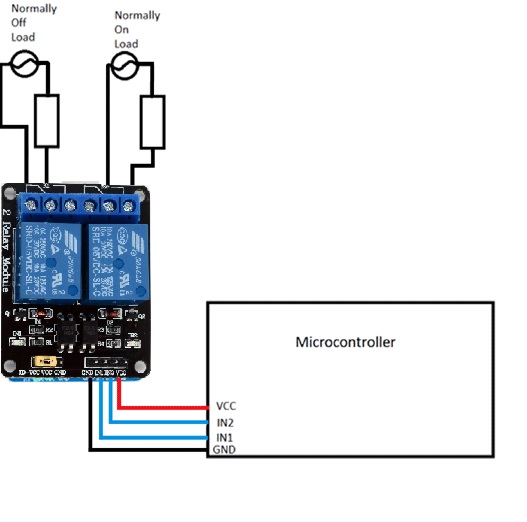
If normally-ON operation is required, the load can instead be connected between COM and NC. The load will then be connected while the relay is inactive and disconnected when the relay is energized.
Library
No dedicated library is required. The relay module is controlled using standard digital GPIO outputs. The microcontroller simply sets the IN1 and IN2 pins HIGH or LOW to control the corresponding relays.
Arduino Example Code
const int RELAY1 = 2;
const int RELAY2 = 3;
void setup() {
 pinMode(RELAY1, OUTPUT);
 pinMode(RELAY2, OUTPUT);
 // Relays OFF at startup
 digitalWrite(RELAY1, LOW);
 digitalWrite(RELAY2, LOW);
}
void loop() {
 // Turn Relay 1 ON
 digitalWrite(RELAY1, HIGH);
 delay(1000);
 // Turn Relay 2 ON
 digitalWrite(RELAY2, HIGH);
 delay(1000);
 // Turn Relay 1 OFF
 digitalWrite(RELAY1, LOW);
 delay(1000);
 // Turn Relay 2 OFF
 digitalWrite(RELAY2, LOW);
 delay(1000);
}Because this is a high-level triggered module, HIGH activates the corresponding relay and LOW deactivates it.
Specifications
| Parameter | Specification |
|---|---|
| Number of Channels | 2 |
| Relay Type | Electromechanical relay |
| Trigger Type | High-Level Trigger |
| Supply Voltage | 3.75V–6V |
| Typical Trigger Current | Approx. 5mA |
| Relay Active Current | Approx. 70mA per relay; approx. 140mA for both relays |
| Maximum Contact Voltage | 250VAC / 30VDC |
| Maximum Contact Current | 10A |
| Relay Contacts | COM, NO, NC |
| Optocouplers | 2 × onboard optocouplers |
| Status Indicators | Power and relay status LEDs |
| Control Interface | IN1, IN2, VCC, GND/SGND |
| Control Method | Digital GPIO |
| Compatible Controllers | Arduino, ESP32, ESP8266, Raspberry Pi interface circuits, PLCs, and other digital control systems |
Resources
Features
- 2 Independent Relay Channels: Two separate relays can be controlled independently from the connected microcontroller.
- High-Level Trigger: Each relay is activated when its corresponding control input is driven HIGH.
- Optocoupler Isolation: Optocouplers are provided on the input side to electrically isolate the controller signal from the relay-driving section.
- High-Current Switching: Each relay provides contacts rated up to 10A at 250VAC or 10A at 30VDC, subject to the relay and load conditions.
- NO and NC Contacts: Each relay provides Normally Open (NO), Normally Closed (NC), and Common (COM) contacts, allowing either normally-off or normally-on load operation.
- LED Indicators: Onboard LEDs provide visual indication of the relay/control status.
- Power Indicator: A dedicated indicator shows when the module is powered.
- High-Impedance Control Input: The control interface is designed to require only a small input current from the connected controller.
- Flexible Power Configuration: The module includes a jumper arrangement that allows the relay/control power configuration to be selected according to the board design.
- Standard Interface: The control pins can be connected to common microcontrollers and control systems.
- Compact Design: Combines two relays, optocouplers, indicators, and control circuitry on a compact PCB.
Principle of Operation
A relay is an electrically controlled mechanical switch. Instead of connecting the microcontroller directly to the high-current load, the microcontroller provides a low-voltage control signal to the relay module. The relay then mechanically switches the electrical connection between its COM, NO, and NC contacts. This module uses a high-level trigger. When the input of a relay channel is driven HIGH, the corresponding relay driver is activated and the relay coil is energized. The relay contacts then change state: the COM contact moves from NC to NO. For example, when a load is connected between COM and NO, the load normally remains OFF while the relay is inactive. When the input signal becomes HIGH, the relay activates and connects COM to NO, turning the load ON.
Alternatively, a load can be connected between COM and NC. In this configuration, the load is normally powered while the relay is inactive. When the relay is activated, COM moves away from NC and the load is switched OFF. The onboard optocouplers transfer the control signal using light rather than a direct electrical connection between the controller-side input circuit and the relay-driving circuitry. This provides galvanic isolation between these sections and can help reduce the transfer of electrical noise and voltage disturbances from the relay/load side toward the controller.
The optocoupler should not, however, be interpreted as automatically making every connection on the module completely isolated. The actual isolation achieved depends on the module's power configuration, jumper arrangement, wiring, and the way the external power supplies are connected.
Pinout
| Pin / Terminal | Function |
|---|---|
| VCC | 5V supply for the module/control section according to the board configuration. |
| GND | Ground connection for the module/power supply. |
| SGND | Signal/control-side ground used according to the module's jumper and isolation configuration. |
| IN1 | High-level control input for Relay 1. |
| IN2 | High-level control input for Relay 2. |
| COM1 | Common contact of Relay 1. |
| NO1 | Normally Open contact of Relay 1. |
| NC1 | Normally Closed contact of Relay 1. |
| COM2 | Common contact of Relay 2. |
| NO2 | Normally Open contact of Relay 2. |
| NC2 | Normally Closed contact of Relay 2. |
Wiring
The control interface can be connected to digital output pins of a compatible microcontroller. The exact GPIO numbers depend on the development board being used.
| Relay Module | Arduino UNO Example | ESP32 Example |
|---|---|---|
| VCC | 5V | 5V/VIN or suitable external supply according to module requirements |
| GND / SGND | GND | GND |
| IN1 | D2 | GPIO18 |
| IN2 | D3 | GPIO19 |
Note: The ESP32 uses 3.3V GPIO logic. Although many 5V relay modules can recognize a 3.3V HIGH signal, compatibility should be verified for the specific module. The relay coil power should also be supplied according to the module's requirements and should not be taken directly from an ESP32 GPIO pin.
Load Connection
For a load that should normally be OFF and turn ON when the relay is activated, connect the load between COM and NO.
For a load that should normally be ON and turn OFF when the relay is activated, connect the load between COM and NC.
| Relay State | COM–NC | COM–NO |
|---|---|---|
| Relay OFF | Connected | Disconnected |
| Relay ON | Disconnected | Connected |
Safety Warning: The relay contacts can be used for high-voltage AC or high-current loads. Mains-voltage wiring must be performed by a qualified person using appropriate insulation, enclosure, fusing, wire gauge, and safety procedures. Never work on energized mains wiring.
Applications
- Home automation systems.
- Arduino and ESP32 projects.
- Industrial control systems.
- PLC interface applications.
- High-current load switching.
- AC lamp and lighting control.
- DC motor switching.
- Water pump control.
- Solenoid valve control.
- Fan and ventilation control.
- Heater control.
- Battery and power-system switching.
- Automation and robotics projects.
- Relay-driven electronic circuits.
Example Circuit
A typical application connects the electrical load to the relay's COM and NO terminals. In this arrangement, the load remains disconnected while the relay is OFF. When the corresponding input is driven HIGH, the relay energizes and connects COM to NO, supplying power to the load.
If normally-ON operation is required, the load can instead be connected between COM and NC. The load will then be connected while the relay is inactive and disconnected when the relay is energized.
Library
No dedicated library is required. The relay module is controlled using standard digital GPIO outputs. The microcontroller simply sets the IN1 and IN2 pins HIGH or LOW to control the corresponding relays.
Arduino Example Code
const int RELAY1 = 2;
const int RELAY2 = 3;
void setup() {
 pinMode(RELAY1, OUTPUT);
 pinMode(RELAY2, OUTPUT);
 // Relays OFF at startup
 digitalWrite(RELAY1, LOW);
 digitalWrite(RELAY2, LOW);
}
void loop() {
 // Turn Relay 1 ON
 digitalWrite(RELAY1, HIGH);
 delay(1000);
 // Turn Relay 2 ON
 digitalWrite(RELAY2, HIGH);
 delay(1000);
 // Turn Relay 1 OFF
 digitalWrite(RELAY1, LOW);
 delay(1000);
 // Turn Relay 2 OFF
 digitalWrite(RELAY2, LOW);
 delay(1000);
}
Because this is a high-level triggered module, HIGH activates the corresponding relay and LOW deactivates it.
Specifications
| Parameter | Specification |
|---|---|
| Number of Channels | 2 |
| Relay Type | Electromechanical relay |
| Trigger Type | High-Level Trigger |
| Supply Voltage | 3.75V–6V |
| Typical Trigger Current | Approx. 5mA |
| Relay Active Current | Approx. 70mA per relay; approx. 140mA for both relays |
| Maximum Contact Voltage | 250VAC / 30VDC |
| Maximum Contact Current | 10A |
| Relay Contacts | COM, NO, NC |
| Optocouplers | 2 × onboard optocouplers |
| Status Indicators | Power and relay status LEDs |
| Control Interface | IN1, IN2, VCC, GND/SGND |
| Control Method | Digital GPIO |
| Compatible Controllers | Arduino, ESP32, ESP8266, Raspberry Pi interface circuits, PLCs, and other digital control systems |