

Features
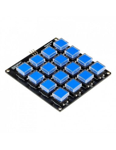
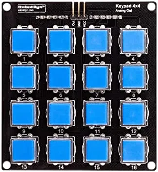
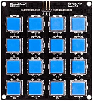
- 16 Push Buttons: Standard 4x4 keypad configuration.
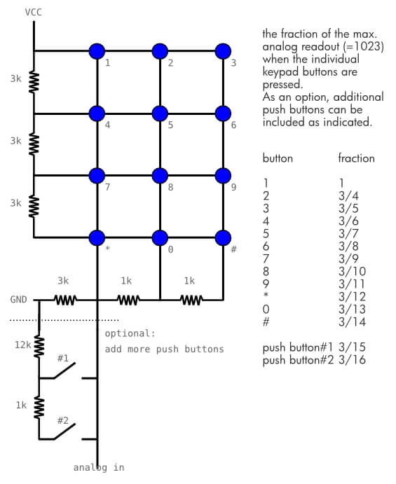
- Analog Output Design: All keys readable via one analog pin.
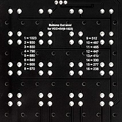
- Integrated Resistor Network: Unique voltage per button press.
- Space-Saving Interface: Minimizes GPIO usage.
- Protective Keycaps: Transparent covers prevent label wear.
- Easy Integration: Compatible with Arduino and other microcontrollers.
Specifications
- Number of Keys: 16 (4x4 matrix)
- Output Type: Analog voltage levels
- Operating Voltage: 3.3V – 5V
- Interface: Single analog signal output
- Board Type: Resistor ladder keypad module
Pinout
- VCC: Power supply (3.3V – 5V)
- GND: Ground
- OUT: Analog signal output
Arduino Wiring
- VCC → 5V (Arduino)
- GND → GND (Arduino)
- OUT → Analog Pin (example: A0)
How It Works
The digital keyboard uses an analog input of the Arduino. So we connect the output of the keyboard to the A0 pin of the microcontroller. The keyboard can be powered by the 5V output of the Arduino.
Example Arduino Code
//Constants
#define nbABtn 16

//Parameters
const int abtnPin = A0;
const int valThresh[nbABtn] = {1000, 900, 820, 750, 660, 620, 585, 540, 500, 475, 455, 425, 370, 300, 260, 200};

void setup() {
  //Init Serial USB
  Serial.begin(9600);
  Serial.println(F("Initialize System"));
}

void loop() {
  readAbtn();
}

void readAbtn() { /* function readAbtn */
  //// Read button states from keypad
  int btnId = getABtn();
  if (btnId) {
    Serial.print("Button pressed : "); Serial.println(btnId);
    delay(200);
  }
}

int getABtn() { /* function getABtn */
  //// Read button states from keypad
  int val = analogRead(abtnPin);
  if (val <= 200) {
    return 0;
  } else {
    for (int i = 0; i < 16; i++) {
      if (val > valThresh[i]) return i + 1;
    }
  }
}
Key Detection Logic (Concept)
Each key generates a different analog reading. To decode button presses, compare the measured value against voltage ranges determined experimentally. Exact values may vary slightly depending on supply voltage and resistor tolerances.
Applications
- Numeric input systems
- Password / access control
- Menu navigation interfaces
- Embedded user controls
- DIY electronics projects
Tips & Information
- Analog values may fluctuate slightly — always use tolerance ranges.
- Supply voltage variations affect readings.
- Debouncing may be required in fast sampling systems.
- Test and record voltage levels for accurate key mapping.
- Ideal for projects requiring minimal pin usage.
Features
- 16 Push Buttons: Standard 4x4 keypad configuration.
- Analog Output Design: All keys readable via one analog pin.
- Integrated Resistor Network: Unique voltage per button press.
- Space-Saving Interface: Minimizes GPIO usage.
- Protective Keycaps: Transparent covers prevent label wear.
- Easy Integration: Compatible with Arduino and other microcontrollers.
Specifications
- Number of Keys: 16 (4x4 matrix)
- Output Type: Analog voltage levels
- Operating Voltage: 3.3V – 5V
- Interface: Single analog signal output
- Board Type: Resistor ladder keypad module
Pinout
- VCC: Power supply (3.3V – 5V)
- GND: Ground
- OUT: Analog signal output
Arduino Wiring
- VCC → 5V (Arduino)
- GND → GND (Arduino)
- OUT → Analog Pin (example: A0)
How It Works
The digital keyboard uses an analog input of the Arduino. So we connect the output of the keyboard to the A0 pin of the microcontroller. The keyboard can be powered by the 5V output of the Arduino.
Example Arduino Code
//Constants
#define nbABtn 16

//Parameters
const int abtnPin = A0;
const int valThresh[nbABtn] = {1000, 900, 820, 750, 660, 620, 585, 540, 500, 475, 455, 425, 370, 300, 260, 200};

void setup() {
  //Init Serial USB
  Serial.begin(9600);
  Serial.println(F("Initialize System"));
}

void loop() {
  readAbtn();
}

void readAbtn() { /* function readAbtn */
  //// Read button states from keypad
  int btnId = getABtn();
  if (btnId) {
    Serial.print("Button pressed : "); Serial.println(btnId);
    delay(200);
  }
}

int getABtn() { /* function getABtn */
  //// Read button states from keypad
  int val = analogRead(abtnPin);
  if (val <= 200) {
    return 0;
  } else {
    for (int i = 0; i < 16; i++) {
      if (val > valThresh[i]) return i + 1;
    }
  }
}
Key Detection Logic (Concept)
Each key generates a different analog reading. To decode button presses, compare the measured value against voltage ranges determined experimentally. Exact values may vary slightly depending on supply voltage and resistor tolerances.
Applications
- Numeric input systems
- Password / access control
- Menu navigation interfaces
- Embedded user controls
- DIY electronics projects
Tips & Information
- Analog values may fluctuate slightly — always use tolerance ranges.
- Supply voltage variations affect readings.
- Debouncing may be required in fast sampling systems.
- Test and record voltage levels for accurate key mapping.
- Ideal for projects requiring minimal pin usage.