Features
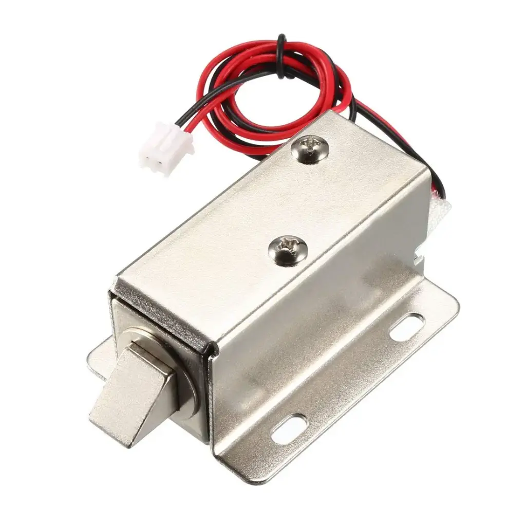
- Slim and compact design for space-saving installation
- Low power consumption with stable locking performance
- Suitable for cabinets, lockers, drawers, luggage, and electric door locks
- Open-frame structure with mounting board for high reliability
- Easy integration into electric and automatic door lock systems
- Adjustable lock tongue direction for flexible installation
Specifications
- Operating Voltage: 12V DC
- Operating Current: 0.6A
- Power Consumption: 7.5W
- Cable Length: 27cm
- Color: Silver
- Dimensions: 23 x 28 x 65mm
How the Lock Works
- When power is applied through the switch, the lock bolt head retracts to 4mm, allowing the door or cabinet to open.
- When power is removed, the internal spring extends the lock tongue to 4mm, securing the door or cabinet in the locked position.
Applications
- Cabinet and locker locking systems
- File cabinets and drawers
- Luggage and storage boxes
- Electric and automatic door locks
- Access control and security systems
Device Wiring
The Electric Magnetic Lock operates on a 12V DC power supply and is controlled by switching the power on or off. It is a normally-locked device, meaning the lock remains engaged when no power is applied and unlocks when 12V DC is supplied.
Power Supply Connection
- Red Wire (+): Connect to the positive terminal of a 12V DC power supply.
- Black Wire (-): Connect to the negative terminal (GND) of the 12V DC power supply.
When 12V DC is applied across these two wires, the lock bolt retracts and the door unlocks.
Switch or Controller Wiring
To control the lock using a switch, relay, access control system, or microcontroller:
- Connect the 12V positive supply to one terminal of the switch or relay.
- Connect the other terminal of the switch or relay to the red wire of the lock.
- Connect the black wire of the lock directly to the power supply GND.
Closing the switch or activating the relay supplies power to the lock and unlocks it. Opening the switch removes power and locks the door.
Relay Module Connection Example
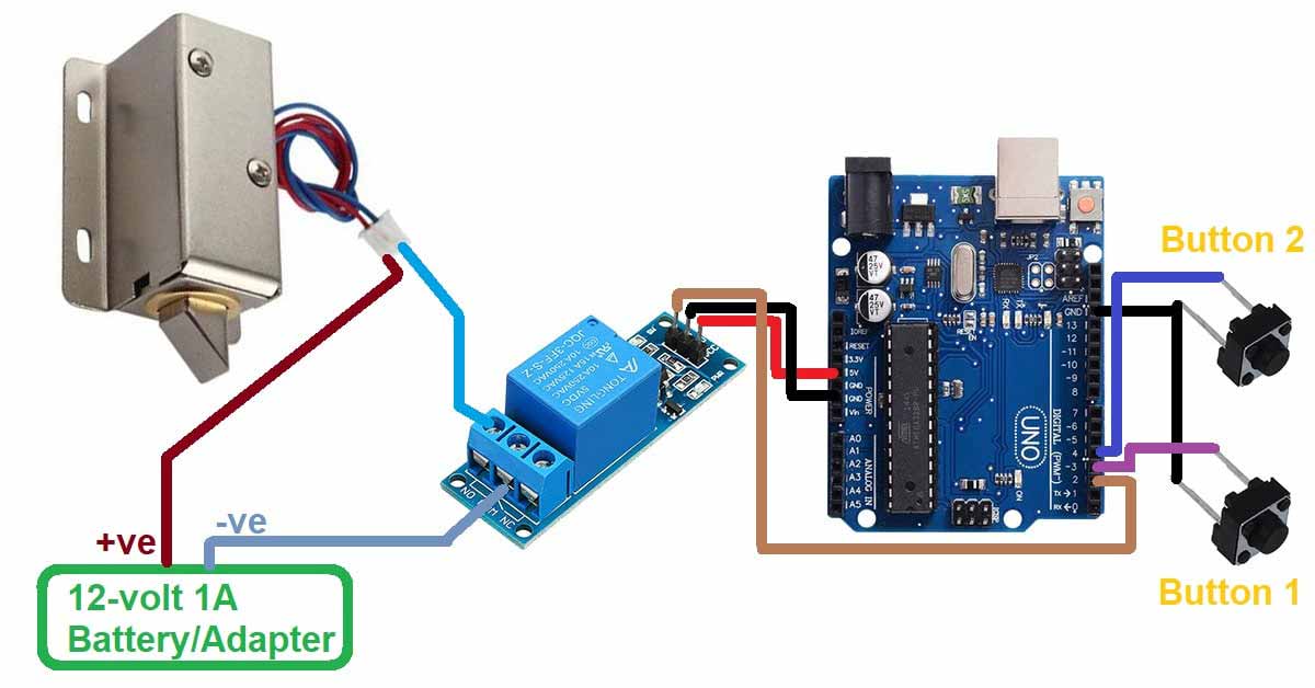
- Relay COM: Connect to +12V from the power supply.
- Relay NO: Connect to the red wire of the lock.
- Lock Black Wire: Connect to power supply GND.
This configuration ensures the lock remains locked by default and unlocks only when the relay is energized.
Operation Summary
- Power OFF: Lock bolt extended, door locked.
- Power ON (12V DC): Lock bolt retracted, door unlocked.
Safety and Installation Notes
- Use a regulated 12V DC power supply capable of delivering at least 0.6A.
- Do not apply AC voltage directly to the lock.
- Ensure correct polarity to avoid damage.
- Secure the lock firmly to prevent mechanical stress on the wiring.
Features
- Slim and compact design for space-saving installation
- Low power consumption with stable locking performance
- Suitable for cabinets, lockers, drawers, luggage, and electric door locks
- Open-frame structure with mounting board for high reliability
- Easy integration into electric and automatic door lock systems
- Adjustable lock tongue direction for flexible installation
Specifications
- Operating Voltage: 12V DC
- Operating Current: 0.6A
- Power Consumption: 7.5W
- Cable Length: 27cm
- Color: Silver
- Dimensions: 23 x 28 x 65mm
How the Lock Works
- When power is applied through the switch, the lock bolt head retracts to 4mm, allowing the door or cabinet to open.
- When power is removed, the internal spring extends the lock tongue to 4mm, securing the door or cabinet in the locked position.
Applications
- Cabinet and locker locking systems
- File cabinets and drawers
- Luggage and storage boxes
- Electric and automatic door locks
- Access control and security systems
Device Wiring
The Electric Magnetic Lock operates on a 12V DC power supply and is controlled by switching the power on or off. It is a normally-locked device, meaning the lock remains engaged when no power is applied and unlocks when 12V DC is supplied.
Power Supply Connection
- Red Wire (+): Connect to the positive terminal of a 12V DC power supply.
- Black Wire (-): Connect to the negative terminal (GND) of the 12V DC power supply.
When 12V DC is applied across these two wires, the lock bolt retracts and the door unlocks.
Switch or Controller Wiring
To control the lock using a switch, relay, access control system, or microcontroller:
- Connect the 12V positive supply to one terminal of the switch or relay.
- Connect the other terminal of the switch or relay to the red wire of the lock.
- Connect the black wire of the lock directly to the power supply GND.
Closing the switch or activating the relay supplies power to the lock and unlocks it. Opening the switch removes power and locks the door.
Relay Module Connection Example
- Relay COM: Connect to +12V from the power supply.
- Relay NO: Connect to the red wire of the lock.
- Lock Black Wire: Connect to power supply GND.
This configuration ensures the lock remains locked by default and unlocks only when the relay is energized.
Operation Summary
- Power OFF: Lock bolt extended, door locked.
- Power ON (12V DC): Lock bolt retracted, door unlocked.
Safety and Installation Notes
- Use a regulated 12V DC power supply capable of delivering at least 0.6A.
- Do not apply AC voltage directly to the lock.
- Ensure correct polarity to avoid damage.
- Secure the lock firmly to prevent mechanical stress on the wiring.