

Features
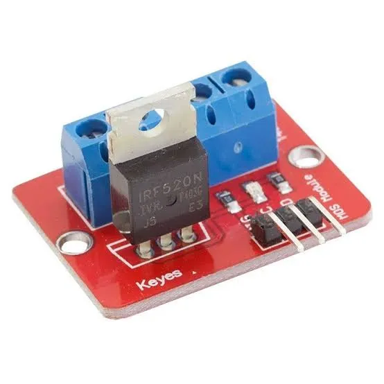
- IRF520 Power MOSFET: Uses an IRF520 N-channel MOSFET as the main switching device.
- Microcontroller Control: Can be controlled using a single digital or PWM output from a compatible controller.
- PWM Support: Supports PWM control for applications such as LED dimming and DC motor speed adjustment.
- Separate Load Supply: Allows the external load to use a supply voltage higher than the microcontroller's operating voltage.
- Wide Load Voltage Range: Suitable for DC loads powered from approximately 5V to 24V.
- Multiple Load Types: Can be used with DC motors, LED lighting, miniature pumps, solenoid valves, and other DC loads.
- Compact Size: The small PCB is suitable for robotics, automation, and embedded projects where space is limited.
- Simple Interface: Provides straightforward VCC, GND, SIG, Vin, and OUT connections.
- Heat Sink Support: A heat sink can be installed when operating the MOSFET at higher load currents.
- Compatible Platforms: Suitable for Arduino, MCU, ARM-based boards, and Raspberry Pi GPIO applications when the required voltage and current conditions are met.
Principle of Operation
The module uses the IRF520 N-channel MOSFET as an electronic switch. The MOSFET is controlled by the voltage applied to its gate through the SIG input. Instead of requiring the microcontroller to supply the current needed by the load, the microcontroller only provides the control signal while the external power supply provides the load current.

When the control signal activates the MOSFET, the MOSFET provides a low-resistance path for current through the connected load. When the control signal is removed, the MOSFET switches OFF and interrupts the load current.
For simple ON/OFF control, the SIG pin can be driven HIGH or LOW. For variable control, a PWM signal can be applied to SIG. PWM rapidly switches the MOSFET ON and OFF at a fixed frequency. By changing the duty cycle, the average power delivered to the load can be adjusted.
For example, a 50% PWM duty cycle keeps the MOSFET ON for approximately half of each PWM period. A DC motor will therefore receive a lower average power level and can operate at a lower speed, while an LED can appear dimmer.
The module itself does not regulate the external load voltage. The load is powered by the voltage connected to the Vin terminal, while the microcontroller provides the control signal through SIG.
Important: The IRF520 is not a true logic-level MOSFET. Although the module can accept a 3.3V control signal, the IRF520 may not fully turn ON at 3.3V, resulting in increased resistance and heat. For high-current applications controlled directly by an ESP32 or other 3.3V MCU, a MOSFET specifically designed for low gate voltages is generally a better choice.
Pinout
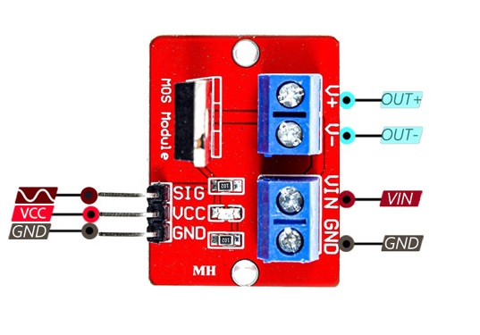
The module provides a simple control and load interface consisting of five main connections.
| Pin | Function |
|---|---|
| VCC | Module control supply, typically 5V. |
| GND | Ground/reference for the control circuit. |
| SIG | Control input. Accepts a digital or PWM signal from the microcontroller. |
| Vin | Positive supply input for the external DC load. |
| OUT | Switched output connection for the external load. |
Wiring
The microcontroller and the external load use their respective power connections. The control signal is connected to SIG, while the load is powered from the external supply connected to Vin and GND.
| IRF520 Module | Arduino UNO Example | ESP32 Example |
|---|---|---|
| VCC | 5V | 5V |
| GND | GND | GND |
| SIG | D6 (PWM) | GPIO18 (PWM) |
| Vin | External DC supply + | External DC supply + |
| OUT | Load connection | Load connection |
The external power supply must be selected according to the requirements of the connected load. The power supply should not be connected directly to a microcontroller GPIO pin.
For a DC motor, connect the motor between the module's OUT connection and the appropriate negative/load return connection according to the module's circuit arrangement. The external motor supply should provide the voltage and current required by the motor.
A suitable flyback diode should be provided when switching inductive loads such as motors, pumps, solenoids, and relays if the module does not already provide adequate suppression. The diode helps protect the MOSFET from voltage spikes generated when the inductive load is switched OFF.
Applications
- DC motor speed control.
- DC motor ON/OFF switching.
- LED strip brightness control.
- PWM LED dimming.
- Miniature DC pump control.
- Solenoid valve control.
- Robotics projects.
- Arduino automation projects.
- Embedded control systems.
- Variable-speed DC load control.
Circuit
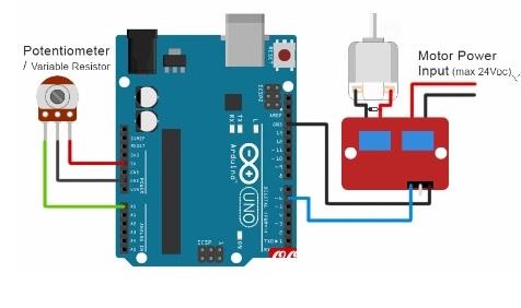
A typical application uses an Arduino or other microcontroller to generate a PWM signal on the SIG input. The external load is powered from a separate DC supply connected to the module's load-power input.
By changing the PWM duty cycle, the controller can adjust the average power delivered to the load. This makes the module useful for controlling the brightness of LED lighting or the speed of a suitable DC motor.
Library
This module does not require a dedicated library. It can be controlled directly using the microcontroller's standard digital output or PWM functions.
Arduino Example Code
const int mosfetPin = 6;
const int potentiometerPin = A0;
void setup() {
 pinMode(mosfetPin, OUTPUT);
}
void loop() {
 int value = analogRead(potentiometerPin);
 // Convert 0-1023 to 0-255 PWM
 int pwmValue = value / 4;
 analogWrite(mosfetPin, pwmValue);
 delay(50);
}In this example, a potentiometer connected to A0 controls the PWM duty cycle applied to the IRF520 module. Turning the potentiometer changes the output power and can therefore adjust the speed of a suitable DC motor or the brightness of an LED load.
Specifications
| Parameter | Specification |
|---|---|
| Transistor | IRF520 N-Channel MOSFET |
| Control Voltage | 3.3V–5V |
| Load Voltage | Approximately 5V–24V DC |
| Recommended Output Current | <1A without additional cooling |
| Higher Current Operation | Up to approximately 5A with appropriate heat sinking and suitable operating conditions |
| Control Method | Digital ON/OFF or PWM |
| Dimensions | Approx. 35 × 25 mm |
| Weight | Approx. 7.5 g |
Important Considerations
The current rating should not be interpreted as a guaranteed continuous 5A operating capability under all conditions. The actual usable current depends on the MOSFET's dissipation, gate voltage, load type, PCB thermal characteristics, ambient temperature, and heat-sink arrangement.
For loads above approximately 1A, additional thermal management may be required. A suitable heat sink should be installed and the MOSFET temperature should be monitored during operation.
Because the IRF520 is not optimized as a low-voltage logic-level MOSFET, it is particularly important to consider the gate-drive voltage when using this module with 3.3V controllers such as ESP32 and ESP8266. For demanding 3.3V applications, a dedicated logic-level MOSFET module may provide better performance and lower heat generation.
Comparison
The IRF520 module and LR7843 MOSFET driver modules are both designed to control DC loads using a microcontroller-generated control signal. However, their MOSFET characteristics are different.
The IRF520 module is based on the IRF520 MOSFET and provides a simple, inexpensive solution for basic DC load and PWM applications. The module does not provide true galvanic isolation between the control and load sides.
An LR7843-based module generally offers better performance when driven by low-voltage logic such as 3.3V because the MOSFET is designed for lower gate-drive voltages. Depending on the specific module, it may also provide additional protection or isolation features.
For simple Arduino projects, LED dimming, and low-current DC motor experiments, the IRF520 module can be a convenient and inexpensive option. For higher-current applications or direct control from 3.3V MCUs, a suitable logic-level MOSFET driver is generally recommended.
Resources
Features
- IRF520 Power MOSFET: Uses an IRF520 N-channel MOSFET as the main switching device.
- Microcontroller Control: Can be controlled using a single digital or PWM output from a compatible controller.
- PWM Support: Supports PWM control for applications such as LED dimming and DC motor speed adjustment.
- Separate Load Supply: Allows the external load to use a supply voltage higher than the microcontroller's operating voltage.
- Wide Load Voltage Range: Suitable for DC loads powered from approximately 5V to 24V.
- Multiple Load Types: Can be used with DC motors, LED lighting, miniature pumps, solenoid valves, and other DC loads.
- Compact Size: The small PCB is suitable for robotics, automation, and embedded projects where space is limited.
- Simple Interface: Provides straightforward VCC, GND, SIG, Vin, and OUT connections.
- Heat Sink Support: A heat sink can be installed when operating the MOSFET at higher load currents.
- Compatible Platforms: Suitable for Arduino, MCU, ARM-based boards, and Raspberry Pi GPIO applications when the required voltage and current conditions are met.
Principle of Operation
The module uses the IRF520 N-channel MOSFET as an electronic switch. The MOSFET is controlled by the voltage applied to its gate through the SIG input. Instead of requiring the microcontroller to supply the current needed by the load, the microcontroller only provides the control signal while the external power supply provides the load current.
When the control signal activates the MOSFET, the MOSFET provides a low-resistance path for current through the connected load. When the control signal is removed, the MOSFET switches OFF and interrupts the load current.
For simple ON/OFF control, the SIG pin can be driven HIGH or LOW. For variable control, a PWM signal can be applied to SIG. PWM rapidly switches the MOSFET ON and OFF at a fixed frequency. By changing the duty cycle, the average power delivered to the load can be adjusted.
For example, a 50% PWM duty cycle keeps the MOSFET ON for approximately half of each PWM period. A DC motor will therefore receive a lower average power level and can operate at a lower speed, while an LED can appear dimmer.
The module itself does not regulate the external load voltage. The load is powered by the voltage connected to the Vin terminal, while the microcontroller provides the control signal through SIG.
Important: The IRF520 is not a true logic-level MOSFET. Although the module can accept a 3.3V control signal, the IRF520 may not fully turn ON at 3.3V, resulting in increased resistance and heat. For high-current applications controlled directly by an ESP32 or other 3.3V MCU, a MOSFET specifically designed for low gate voltages is generally a better choice.
Pinout
The module provides a simple control and load interface consisting of five main connections.
| Pin | Function |
|---|---|
| VCC | Module control supply, typically 5V. |
| GND | Ground/reference for the control circuit. |
| SIG | Control input. Accepts a digital or PWM signal from the microcontroller. |
| Vin | Positive supply input for the external DC load. |
| OUT | Switched output connection for the external load. |
Wiring
The microcontroller and the external load use their respective power connections. The control signal is connected to SIG, while the load is powered from the external supply connected to Vin and GND.
| IRF520 Module | Arduino UNO Example | ESP32 Example |
|---|---|---|
| VCC | 5V | 5V |
| GND | GND | GND |
| SIG | D6 (PWM) | GPIO18 (PWM) |
| Vin | External DC supply + | External DC supply + |
| OUT | Load connection | Load connection |
The external power supply must be selected according to the requirements of the connected load. The power supply should not be connected directly to a microcontroller GPIO pin.
For a DC motor, connect the motor between the module's OUT connection and the appropriate negative/load return connection according to the module's circuit arrangement. The external motor supply should provide the voltage and current required by the motor.
A suitable flyback diode should be provided when switching inductive loads such as motors, pumps, solenoids, and relays if the module does not already provide adequate suppression. The diode helps protect the MOSFET from voltage spikes generated when the inductive load is switched OFF.
Applications
- DC motor speed control.
- DC motor ON/OFF switching.
- LED strip brightness control.
- PWM LED dimming.
- Miniature DC pump control.
- Solenoid valve control.
- Robotics projects.
- Arduino automation projects.
- Embedded control systems.
- Variable-speed DC load control.
Circuit
A typical application uses an Arduino or other microcontroller to generate a PWM signal on the SIG input. The external load is powered from a separate DC supply connected to the module's load-power input.
By changing the PWM duty cycle, the controller can adjust the average power delivered to the load. This makes the module useful for controlling the brightness of LED lighting or the speed of a suitable DC motor.
Library
This module does not require a dedicated library. It can be controlled directly using the microcontroller's standard digital output or PWM functions.
Arduino Example Code
const int mosfetPin = 6;
const int potentiometerPin = A0;
void setup() {
 pinMode(mosfetPin, OUTPUT);
}
void loop() {
 int value = analogRead(potentiometerPin);
 // Convert 0-1023 to 0-255 PWM
 int pwmValue = value / 4;
 analogWrite(mosfetPin, pwmValue);
 delay(50);
}
In this example, a potentiometer connected to A0 controls the PWM duty cycle applied to the IRF520 module. Turning the potentiometer changes the output power and can therefore adjust the speed of a suitable DC motor or the brightness of an LED load.
Specifications
| Parameter | Specification |
|---|---|
| Transistor | IRF520 N-Channel MOSFET |
| Control Voltage | 3.3V–5V |
| Load Voltage | Approximately 5V–24V DC |
| Recommended Output Current | <1A without additional cooling |
| Higher Current Operation | Up to approximately 5A with appropriate heat sinking and suitable operating conditions |
| Control Method | Digital ON/OFF or PWM |
| Dimensions | Approx. 35 × 25 mm |
| Weight | Approx. 7.5 g |
Important Considerations
The current rating should not be interpreted as a guaranteed continuous 5A operating capability under all conditions. The actual usable current depends on the MOSFET's dissipation, gate voltage, load type, PCB thermal characteristics, ambient temperature, and heat-sink arrangement.
For loads above approximately 1A, additional thermal management may be required. A suitable heat sink should be installed and the MOSFET temperature should be monitored during operation.
Because the IRF520 is not optimized as a low-voltage logic-level MOSFET, it is particularly important to consider the gate-drive voltage when using this module with 3.3V controllers such as ESP32 and ESP8266. For demanding 3.3V applications, a dedicated logic-level MOSFET module may provide better performance and lower heat generation.
Comparison
The IRF520 module and LR7843 MOSFET driver modules are both designed to control DC loads using a microcontroller-generated control signal. However, their MOSFET characteristics are different.
The IRF520 module is based on the IRF520 MOSFET and provides a simple, inexpensive solution for basic DC load and PWM applications. The module does not provide true galvanic isolation between the control and load sides.
An LR7843-based module generally offers better performance when driven by low-voltage logic such as 3.3V because the MOSFET is designed for lower gate-drive voltages. Depending on the specific module, it may also provide additional protection or isolation features.
For simple Arduino projects, LED dimming, and low-current DC motor experiments, the IRF520 module can be a convenient and inexpensive option. For higher-current applications or direct control from 3.3V MCUs, a suitable logic-level MOSFET driver is generally recommended.