Features:
- 10-Bit Resolution: With a resolution of 1024 levels, the TLC5615 module provides precise and accurate analog signal output, making it suitable for a wide range of applications.
- Serial Interface: The module supports either SPI or I2C communication protocols, making it easy to interface with microcontrollers or other digital devices.
- Wide Supply Voltage Range: The TLC5615 can operate on a supply voltage range of 2.7V to 5.5V, making it compatible with a variety of power sources.
- Output Voltage Range: The module provides an output voltage range of 0V to VDD, enabling it to generate analog signals with a range that is proportional to the supply voltage.
- Low Power Consumption: The TLC5615 is designed for low power consumption, making it suitable for battery-powered applications.
- High Accuracy and Stability: The TLC5615 is designed for high accuracy and stability, ensuring that the output signals are precise and consistent over time.
- Easy to Use: The TLC5615 module is easy to use, with simple interfaces and documentation that make it straightforward to integrate into a wide range of applications.
Principle of Work:
The DAC TLC5615 10-Bit Serial Module operates on the principle of Digital-to-Analog Conversion (DAC). This module converts a digital input signal into an equivalent analog output signal. The conversion process is accomplished by using an integrated circuit (IC) with an internal digital-to-analog converter (DAC). The digital input signal is received by the module through a serial interface, 3-Wire Serial This input signal is then processed by the internal DAC to generate a corresponding analog output signal. The analog output signal is proportional to the digital input signal and can be used to control various types of analog devices, such as analog sensors, actuators, or displays. The resolution of the DAC determines the number of levels of the output signal, with a higher resolution resulting in a more precise output signal. The TLC5615 module has a resolution of 10 bits, providing 1024 levels of output, which makes it suitable for a wide range of applications.
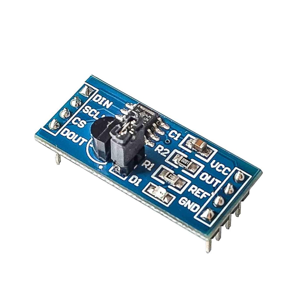
Pinout of the Module:

- VCC: Power supply pin, typically connected to a positive voltage source.
- GND: Ground pin, typically connected to the ground of the circuit.
- REF: Reference voltage input pin, used to set the reference voltage for the digital-to-analog conversion.
- CS: Chip select pin, used to select the device for communication.
- DOUT: Serial data output pin, used to output the serial data from the module.
- DIN: Serial data input
- OUT: Analog output pin, outputs the analog equivalent of the digital input data.
Applications:
- Data acquisition systems: The TLC5615 can be used to convert digital signals into analog signals, making it useful in data acquisition systems where digital signals need to be transmitted and processed as analog signals.
- Industrial control systems: The TLC5615 can be used in industrial control systems to convert digital signals into analog signals that can be used to control and regulate processes, such as motor control and temperature control.
- Test and measurement equipment: The TLC5615 can be used in test and measurement equipment, such as oscilloscopes and function generators, to convert digital signals into analog signals for display or for testing purposes.
- Medical equipment: The TLC5615 can be used in medical equipment, such as patient monitoring systems, to convert digital signals into analog signals for display or for further processing.
- Audio systems: The TLC5615 can be used in audio systems, such as digital-to-analog converters, to convert digital audio signals into analog audio signals that can be played back through speakers.
Circuit:
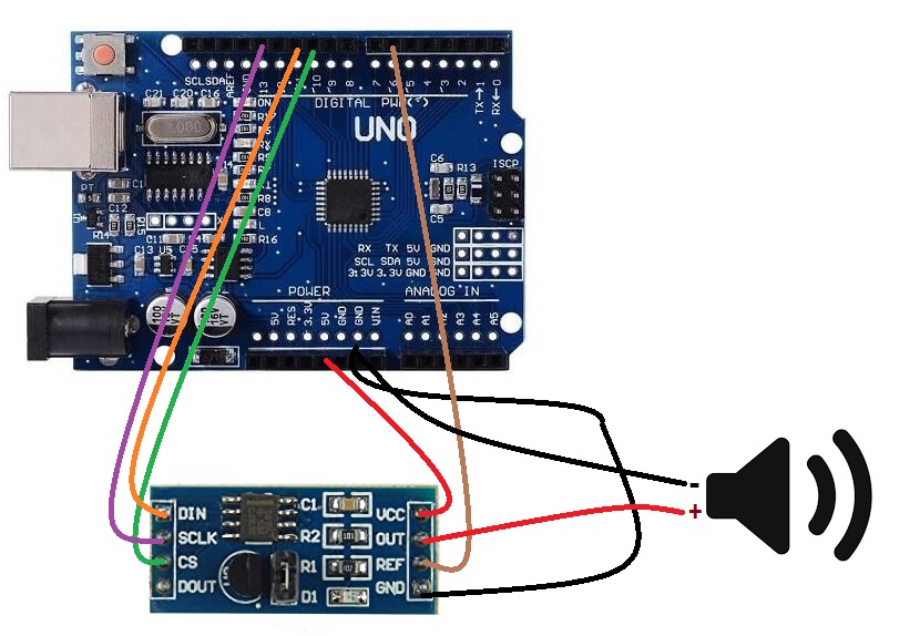
Connect the TLC5615 to the Arduino as follows:
TLC5615 pin 1 (VCC) to 5V
TLC5615 pin 2 (GND) to GND
TLC5615 pin 3 (CS) to digital pin 10
TLC5615 pin 4 (CLK) to digital pin 13
TLC5615 pin 5 (DIN) to digital pin 11
TLC5615 pin 6 (REF) to GND
TLC5615 pin 7 (Out) to the positive terminal of a speaker
The negative terminal of the speaker to GND
Library:
No need for Library.
Code:
Generating a sine wave and outputting it to the TLC5615 digital-to-analog converter (DAC)
#define CS 10
#define CLK 13
#define DIN 11
void setup() {
 // Set the CS, CLK, and DIN pins as outputs
 pinMode(CS, OUTPUT);
 pinMode(CLK, OUTPUT);
 pinMode(DIN, OUTPUT);
 // Initialize the TLC5615
 digitalWrite(CS, HIGH);
 digitalWrite(CLK, LOW);
 digitalWrite(DIN, LOW);
}
void loop() {
 // Generate a sine wave to output to the TLC5615
 for (int i = 0; i < 1024; i++) {
 int sample = 512 + (512 * sin(2 * PI * (i / 1024.0)));
 // Output the sample to the TLC5615
 digitalWrite(CS, LOW);
 shiftOut(DIN, CLK, MSBFIRST, sample >> 2);
 shiftOut(DIN, CLK, MSBFIRST, sample << 6);
 digitalWrite(CS, HIGH);
 }
}
-
Load the code into the Arduino using the Arduino Integrated Development Environment (IDE). You can copy and paste the code into the Arduino IDE and upload it to the Arduino.
-
Once the code has been uploaded to the Arduino, it will automatically generate a sine wave and output it to the TLC5615 DAC. The TLC5615 will then convert the digital signal into an analog signal, which can be heard through the speaker connected to the "Out" pin.
Technical Details:
- Resolution: 10-bit
- Operating Voltage: 4.5 V to 5.5 V
- Output Voltage Range: 0 V to VCC
- Current Output: 10 mA
- Operating Temperature Range: -40 °C to +85 °C
- Package Type: SOIC
- Maximum Clock Frequency: 20 MHz
Resources:
Features:
- 10-Bit Resolution: With a resolution of 1024 levels, the TLC5615 module provides precise and accurate analog signal output, making it suitable for a wide range of applications.
- Serial Interface: The module supports either SPI or I2C communication protocols, making it easy to interface with microcontrollers or other digital devices.
- Wide Supply Voltage Range: The TLC5615 can operate on a supply voltage range of 2.7V to 5.5V, making it compatible with a variety of power sources.
- Output Voltage Range: The module provides an output voltage range of 0V to VDD, enabling it to generate analog signals with a range that is proportional to the supply voltage.
- Low Power Consumption: The TLC5615 is designed for low power consumption, making it suitable for battery-powered applications.
- High Accuracy and Stability: The TLC5615 is designed for high accuracy and stability, ensuring that the output signals are precise and consistent over time.
- Easy to Use: The TLC5615 module is easy to use, with simple interfaces and documentation that make it straightforward to integrate into a wide range of applications.
Principle of Work:
The DAC TLC5615 10-Bit Serial Module operates on the principle of Digital-to-Analog Conversion (DAC). This module converts a digital input signal into an equivalent analog output signal. The conversion process is accomplished by using an integrated circuit (IC) with an internal digital-to-analog converter (DAC). The digital input signal is received by the module through a serial interface, 3-Wire Serial This input signal is then processed by the internal DAC to generate a corresponding analog output signal. The analog output signal is proportional to the digital input signal and can be used to control various types of analog devices, such as analog sensors, actuators, or displays. The resolution of the DAC determines the number of levels of the output signal, with a higher resolution resulting in a more precise output signal. The TLC5615 module has a resolution of 10 bits, providing 1024 levels of output, which makes it suitable for a wide range of applications.
Pinout of the Module:
- VCC: Power supply pin, typically connected to a positive voltage source.
- GND: Ground pin, typically connected to the ground of the circuit.
- REF: Reference voltage input pin, used to set the reference voltage for the digital-to-analog conversion.
- CS: Chip select pin, used to select the device for communication.
- DOUT: Serial data output pin, used to output the serial data from the module.
- DIN: Serial data input
- OUT: Analog output pin, outputs the analog equivalent of the digital input data.
Applications:
- Data acquisition systems: The TLC5615 can be used to convert digital signals into analog signals, making it useful in data acquisition systems where digital signals need to be transmitted and processed as analog signals.
- Industrial control systems: The TLC5615 can be used in industrial control systems to convert digital signals into analog signals that can be used to control and regulate processes, such as motor control and temperature control.
- Test and measurement equipment: The TLC5615 can be used in test and measurement equipment, such as oscilloscopes and function generators, to convert digital signals into analog signals for display or for testing purposes.
- Medical equipment: The TLC5615 can be used in medical equipment, such as patient monitoring systems, to convert digital signals into analog signals for display or for further processing.
- Audio systems: The TLC5615 can be used in audio systems, such as digital-to-analog converters, to convert digital audio signals into analog audio signals that can be played back through speakers.
Circuit:
Connect the TLC5615 to the Arduino as follows:
TLC5615 pin 1 (VCC) to 5V
TLC5615 pin 2 (GND) to GND
TLC5615 pin 3 (CS) to digital pin 10
TLC5615 pin 4 (CLK) to digital pin 13
TLC5615 pin 5 (DIN) to digital pin 11
TLC5615 pin 6 (REF) to GND
TLC5615 pin 7 (Out) to the positive terminal of a speaker
The negative terminal of the speaker to GND
Library:
No need for Library.
Code:
Generating a sine wave and outputting it to the TLC5615 digital-to-analog converter (DAC)
#define CS 10
#define CLK 13
#define DIN 11
void setup() {
 // Set the CS, CLK, and DIN pins as outputs
 pinMode(CS, OUTPUT);
 pinMode(CLK, OUTPUT);
 pinMode(DIN, OUTPUT);
 // Initialize the TLC5615
 digitalWrite(CS, HIGH);
 digitalWrite(CLK, LOW);
 digitalWrite(DIN, LOW);
}
void loop() {
 // Generate a sine wave to output to the TLC5615
 for (int i = 0; i < 1024; i++) {
 int sample = 512 + (512 * sin(2 * PI * (i / 1024.0)));
 // Output the sample to the TLC5615
 digitalWrite(CS, LOW);
 shiftOut(DIN, CLK, MSBFIRST, sample >> 2);
 shiftOut(DIN, CLK, MSBFIRST, sample << 6);
 digitalWrite(CS, HIGH);
 }
}
-
Load the code into the Arduino using the Arduino Integrated Development Environment (IDE). You can copy and paste the code into the Arduino IDE and upload it to the Arduino.
-
Once the code has been uploaded to the Arduino, it will automatically generate a sine wave and output it to the TLC5615 DAC. The TLC5615 will then convert the digital signal into an analog signal, which can be heard through the speaker connected to the "Out" pin.
Technical Details:
- Resolution: 10-bit
- Operating Voltage: 4.5 V to 5.5 V
- Output Voltage Range: 0 V to VCC
- Current Output: 10 mA
- Operating Temperature Range: -40 °C to +85 °C
- Package Type: SOIC
- Maximum Clock Frequency: 20 MHz