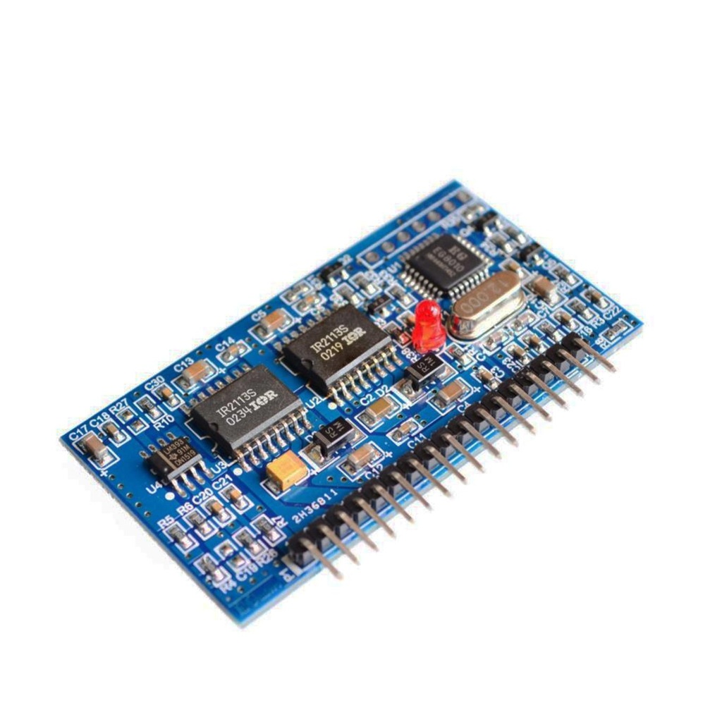
Features
- 5V single power supply
- Four pure sine wave output modes:
- Fixed 50Hz
- Fixed 60Hz
- Adjustable 0–100Hz
- Adjustable 0–400Hz
- Unipolar and bipolar modulation
- Dead-time control with 4 options: 300ns, 500ns, 1.0µs, 1.5µs
- External 12MHz crystal oscillator, 23.4kHz PWM carrier frequency
- Real-time voltage, current, and temperature feedback
- Protection features: overvoltage, undervoltage, overcurrent, overheating
- Soft-start mode with 1s response time
- RS232 serial communication to configure output voltage, frequency, temperature, and current monitoring
Specification
- Product Name: Pure Sine Wave Inverter Driver Board
- Supply Voltage: DC 5V
- Output Frequency: 50 / 60 / 0–100 / 0–400 Hz
- Output Voltage: AC 187V (Max)
- Working Temperature: -25°C to 85°C
- Working Humidity: 5% ~ 95% RH
- Dimensions: 63 x 40 x 10 mm

Applications
- Single-Phase Inverter: Converts DC to AC with pure sine wave output, ideal for solar systems and off-grid setups.
- PV/Wind Power Inverter: Suitable for renewable energy systems.
- UPS Systems: Provides stable backup power for sensitive equipment.
- Digital Generator: Used in telecom and data center backup systems.
- Motor Speed Control: Controls single-phase motor speed by varying AC frequency.
- Sine Wave Dimmer: Adjusts light brightness by modifying AC voltage or current.
- Sine Wave Regulator: Stabilizes voltage or frequency in power supplies.
- Sine Wave Generator: Used in testing and calibration tasks.
Pin Connections
| Abbreviation | Full Name | Description |
|---|---|---|
| IFB | Inverter Feedback | Signal input to control the inverter output |
| GND | Ground | Common reference point for electrical signals |
| IL0 | Inverter Low Side | Output for a phase of the inverter |
| VS1 | Voltage Sense 1 | Signal input for measuring voltage |
| IH0 | Inverter High Side | Output for a phase of the inverter |
| 2L0 | Second Low Side | Output for another phase of the inverter |
| VS2 | Voltage Sense 2 | Signal input for measuring voltage |
| 2H0 | Second High Side | Output for another phase of the inverter |
| +12V | Positive 12 Volt | Power supply voltage |
| +5V | Positive 5 Volt | Power supply voltage |
| UFB | Unipolar Feedback | Signal input for unipolar modulation |
| FANCTR | Fan Control | Signal output to control a fan |

References
Features
- 5V single power supply
- Four pure sine wave output modes:
- Fixed 50Hz
- Fixed 60Hz
- Adjustable 0–100Hz
- Adjustable 0–400Hz
- Unipolar and bipolar modulation
- Dead-time control with 4 options: 300ns, 500ns, 1.0µs, 1.5µs
- External 12MHz crystal oscillator, 23.4kHz PWM carrier frequency
- Real-time voltage, current, and temperature feedback
- Protection features: overvoltage, undervoltage, overcurrent, overheating
- Soft-start mode with 1s response time
- RS232 serial communication to configure output voltage, frequency, temperature, and current monitoring
Specification
- Product Name: Pure Sine Wave Inverter Driver Board
- Supply Voltage: DC 5V
- Output Frequency: 50 / 60 / 0–100 / 0–400 Hz
- Output Voltage: AC 187V (Max)
- Working Temperature: -25°C to 85°C
- Working Humidity: 5% ~ 95% RH
- Dimensions: 63 x 40 x 10 mm
Applications
- Single-Phase Inverter: Converts DC to AC with pure sine wave output, ideal for solar systems and off-grid setups.
- PV/Wind Power Inverter: Suitable for renewable energy systems.
- UPS Systems: Provides stable backup power for sensitive equipment.
- Digital Generator: Used in telecom and data center backup systems.
- Motor Speed Control: Controls single-phase motor speed by varying AC frequency.
- Sine Wave Dimmer: Adjusts light brightness by modifying AC voltage or current.
- Sine Wave Regulator: Stabilizes voltage or frequency in power supplies.
- Sine Wave Generator: Used in testing and calibration tasks.
Pin Connections
| Abbreviation | Full Name | Description |
|---|---|---|
| IFB | Inverter Feedback | Signal input to control the inverter output |
| GND | Ground | Common reference point for electrical signals |
| IL0 | Inverter Low Side | Output for a phase of the inverter |
| VS1 | Voltage Sense 1 | Signal input for measuring voltage |
| IH0 | Inverter High Side | Output for a phase of the inverter |
| 2L0 | Second Low Side | Output for another phase of the inverter |
| VS2 | Voltage Sense 2 | Signal input for measuring voltage |
| 2H0 | Second High Side | Output for another phase of the inverter |
| +12V | Positive 12 Volt | Power supply voltage |
| +5V | Positive 5 Volt | Power supply voltage |
| UFB | Unipolar Feedback | Signal input for unipolar modulation |
| FANCTR | Fan Control | Signal output to control a fan |