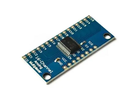
Features
- Based on the 74HC4067 16-channel analog multiplexer/demultiplexer IC.
- Expands a single signal pin to communicate with up to 16 channels.
- Supports both analog and digital signals.
- Bidirectional signal switching for flexible input or output operation.
- Requires only four address pins plus one signal pin.
- Enable (EN) pin allows all channels to be disconnected.
- Low ON resistance for minimal signal loss.
- Break-before-make switching prevents channel shorting during selection.
- Breadboard-friendly breakout board with clearly labeled pins.
- Compatible with Arduino, ESP32, STM32, Raspberry Pi, and other microcontrollers.
Principle of Operation
The module uses the 74HC4067 CMOS analog switch IC to connect one common signal pin (SIG) to one of sixteen independent channels (C0–C15). The desired channel is selected by setting the four address pins (S0–S3) to the corresponding binary value.
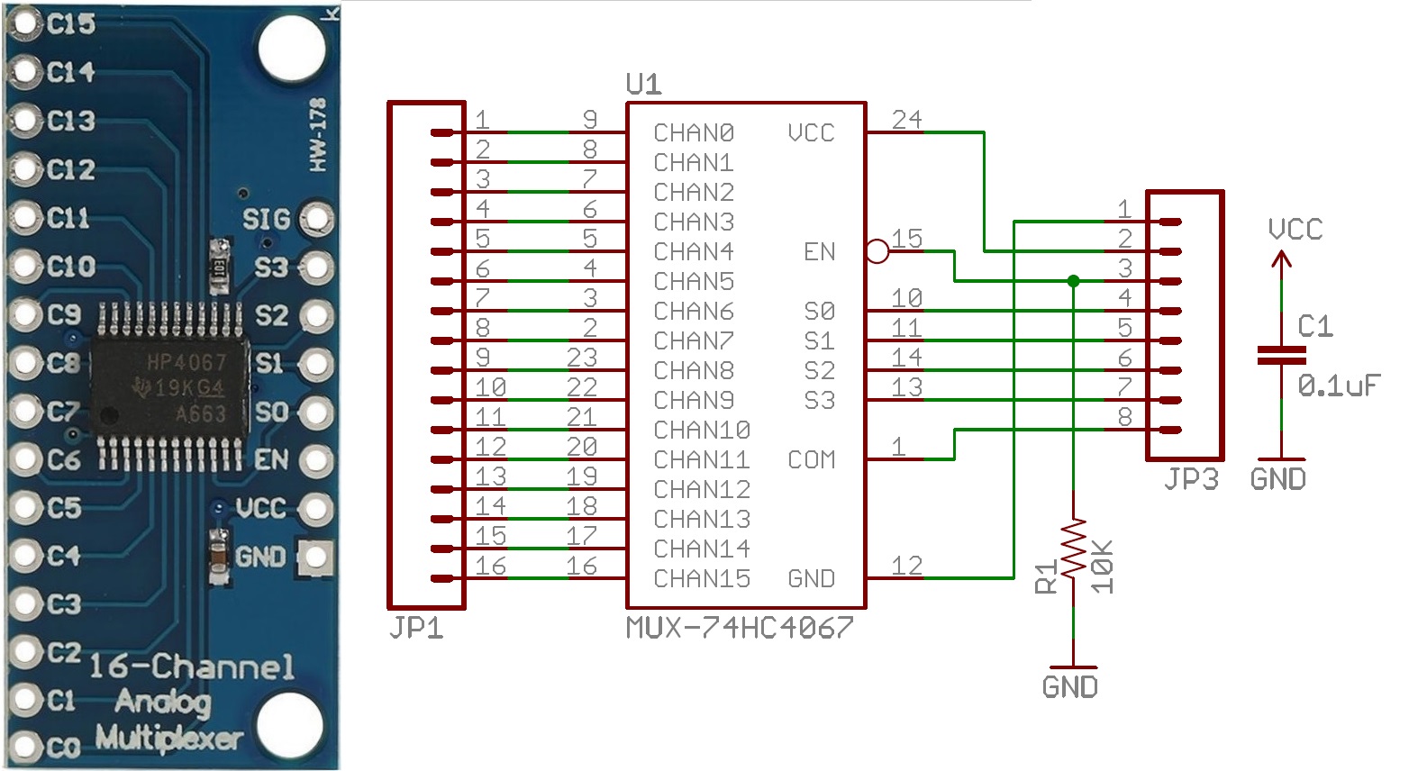
When the Enable (EN) pin is LOW, the selected channel is connected to the SIG pin while all other channels remain isolated. When EN is HIGH, all channels are disconnected. Since the switch is bidirectional, signals can flow in either direction, making the module suitable for both analog measurements and digital communication.

Pinout

| Pin | Description |
|---|---|
| VCC | Power supply (2V–6V) |
| GND | Ground |
| SIG | Common analog/digital input or output |
| EN | Enable input (Active LOW) |
| S0 | Address select bit 0 (LSB) |
| S1 | Address select bit 1 |
| S2 | Address select bit 2 |
| S3 | Address select bit 3 (MSB) |
| C0 – C15 | Individual analog/digital channels |
Wiring (Arduino Example)

| 74HC4067 | Arduino UNO |
|---|---|
| VCC | 5V |
| GND | GND |
| S0 | 11 |
| S1 | 10 |
| S2 | 9 |
| S3 | 8 |
| EN | GND (Always Enabled) |
| SIG | A0 |
Sample code:
// Define Multiplexer Control Pins (Updated Layout)
const int s0 = 11;
const int s1 = 10;
const int s2 = 9;
const int s3 = 8;

// Define Multiplexer Signal Pin
const int sigPin = A0;

void setup() {
  // Configure control pins as outputs
  pinMode(s0, OUTPUT);
  pinMode(s1, OUTPUT);
  pinMode(s2, OUTPUT);
  pinMode(s3, OUTPUT);

  // Initialize Serial Monitor
  Serial.begin(9600);
}

void loop() {
  // Loop through all 16 channels (0 to 15)
  for (int channel = 0; channel < 16; channel++) {
    int val = readMux(channel);

    // Print the channel and its value to the Serial Monitor
    Serial.print("Ch ");
    Serial.print(channel);
    Serial.print(": ");
    Serial.print(val);
    Serial.print("\t");
  }
  Serial.println(); // New line after printing all 16 channels

  delay(500); // Wait half a second before the next read
}

// Function to select and read a specific multiplexer channel
int readMux(int channel) {
  // Set the 4 control pins using binary bit manipulation
  digitalWrite(s0, bitRead(channel, 0));
  digitalWrite(s1, bitRead(channel, 1));
  digitalWrite(s2, bitRead(channel, 2));
  digitalWrite(s3, bitRead(channel, 3));

  // Read the analog value from the selected channel
  return analogRead(sigPin);
}
Applications
- Expanding analog input channels.
- Reading multiple sensors with a single ADC pin.
- Data acquisition systems.
- Signal routing and switching.
- Robotics and automation.
- Industrial monitoring.
- Audio signal multiplexing.
- Test and measurement equipment.
Specifications
| Parameter | Value |
|---|---|
| IC | 74HC4067 / CD74HC4067 |
| Number of Channels | 16 |
| Operating Voltage | 2V – 6V |
| Logic Control Inputs | S0, S1, S2, S3, EN |
| Signal Type | Analog and Digital |
| Signal Direction | Bidirectional |
| ON Resistance | Typical 70Ω @ 4.5V, 60Ω @ 6V |
| Switching Time | Break-before-make, approximately 6ns @ 4.5V |
| Operating Temperature | -55°C to +125°C |
| Module Dimensions | Approximately 25 × 18 mm |
Resources
- Texas Instruments CD74HC4067 Datasheet
- MUX74HC4067 Arduino Library (GitHub)
- Arduino Language Reference
Features
- Based on the 74HC4067 16-channel analog multiplexer/demultiplexer IC.
- Expands a single signal pin to communicate with up to 16 channels.
- Supports both analog and digital signals.
- Bidirectional signal switching for flexible input or output operation.
- Requires only four address pins plus one signal pin.
- Enable (EN) pin allows all channels to be disconnected.
- Low ON resistance for minimal signal loss.
- Break-before-make switching prevents channel shorting during selection.
- Breadboard-friendly breakout board with clearly labeled pins.
- Compatible with Arduino, ESP32, STM32, Raspberry Pi, and other microcontrollers.
Principle of Operation
The module uses the 74HC4067 CMOS analog switch IC to connect one common signal pin (SIG) to one of sixteen independent channels (C0–C15). The desired channel is selected by setting the four address pins (S0–S3) to the corresponding binary value.
When the Enable (EN) pin is LOW, the selected channel is connected to the SIG pin while all other channels remain isolated. When EN is HIGH, all channels are disconnected. Since the switch is bidirectional, signals can flow in either direction, making the module suitable for both analog measurements and digital communication.
Pinout
| Pin | Description |
|---|---|
| VCC | Power supply (2V–6V) |
| GND | Ground |
| SIG | Common analog/digital input or output |
| EN | Enable input (Active LOW) |
| S0 | Address select bit 0 (LSB) |
| S1 | Address select bit 1 |
| S2 | Address select bit 2 |
| S3 | Address select bit 3 (MSB) |
| C0 – C15 | Individual analog/digital channels |
Wiring (Arduino Example)
| 74HC4067 | Arduino UNO |
|---|---|
| VCC | 5V |
| GND | GND |
| S0 | 11 |
| S1 | 10 |
| S2 | 9 |
| S3 | 8 |
| EN | GND (Always Enabled) |
| SIG | A0 |
Sample code:
// Define Multiplexer Control Pins (Updated Layout)
const int s0 = 11;
const int s1 = 10;
const int s2 = 9;
const int s3 = 8;

// Define Multiplexer Signal Pin
const int sigPin = A0;

void setup() {
  // Configure control pins as outputs
  pinMode(s0, OUTPUT);
  pinMode(s1, OUTPUT);
  pinMode(s2, OUTPUT);
  pinMode(s3, OUTPUT);

  // Initialize Serial Monitor
  Serial.begin(9600);
}

void loop() {
  // Loop through all 16 channels (0 to 15)
  for (int channel = 0; channel < 16; channel++) {
    int val = readMux(channel);

    // Print the channel and its value to the Serial Monitor
    Serial.print("Ch ");
    Serial.print(channel);
    Serial.print(": ");
    Serial.print(val);
    Serial.print("\t");
  }
  Serial.println(); // New line after printing all 16 channels

  delay(500); // Wait half a second before the next read
}

// Function to select and read a specific multiplexer channel
int readMux(int channel) {
  // Set the 4 control pins using binary bit manipulation
  digitalWrite(s0, bitRead(channel, 0));
  digitalWrite(s1, bitRead(channel, 1));
  digitalWrite(s2, bitRead(channel, 2));
  digitalWrite(s3, bitRead(channel, 3));

  // Read the analog value from the selected channel
  return analogRead(sigPin);
}
Applications
- Expanding analog input channels.
- Reading multiple sensors with a single ADC pin.
- Data acquisition systems.
- Signal routing and switching.
- Robotics and automation.
- Industrial monitoring.
- Audio signal multiplexing.
- Test and measurement equipment.
Specifications
| Parameter | Value |
|---|---|
| IC | 74HC4067 / CD74HC4067 |
| Number of Channels | 16 |
| Operating Voltage | 2V – 6V |
| Logic Control Inputs | S0, S1, S2, S3, EN |
| Signal Type | Analog and Digital |
| Signal Direction | Bidirectional |
| ON Resistance | Typical 70Ω @ 4.5V, 60Ω @ 6V |
| Switching Time | Break-before-make, approximately 6ns @ 4.5V |
| Operating Temperature | -55°C to +125°C |
| Module Dimensions | Approximately 25 × 18 mm |